A.O. Smith Burkay HW-300 Installation Operation & Maintenance Download Page 54

54

54

54

54

54

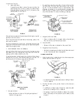
To adjust the flow rate setting:

1.

Remove the flow switch cover.

2.

For higher flow rate—turn the range adjusting screw clockwise.

3.

For lower flow rate—turn the range adjusting screw
counter-clockwise.


 CAUTION

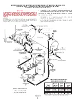
The switch is factory set at approximately the minimum flow rate,
see Table II.  It must not be set lower than the factory setting as this
may result in the switch failing to return at a “no flow” condition.

4.

Replace the flow switch cover.

Where units are installed in multiples, each boiler must be
individually protected by a safety flow switch.

SAFETY RELIEF VALVE MAINTENANCE

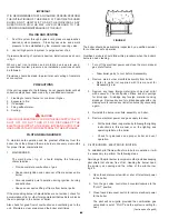
Every six months the system safety relief valves should be checked
to ensure that they are in operating condition.  To check a relief
valve, lift the lever at the end of the valve several times.  The valve
should seat properly and operate freely.


 CAUTION

BEFORE MANUALLY OPERATING A RELIEF VALVE, MAKE SURE
THAT A DRAIN LINE HAS BEEN ATTACHED TO THE VALVE TO
DIRECT THE DISCHARGE TO AN OPEN DRAIN.  FAILURE TO
TAKE THIS PRECAUTION COULD MEAN CONTACT WITH
EXTREMELY HOT WATER EXITING THE VALVE DURING THIS
CHECK OPERATION.

If a relief valve discharges periodically or continuously, it may be
due to thermal expansion of water in a closed water supply system,
or, it may be due to thermal expansion of water in a closed water
supply system, or, it may be due to a faulty relief valve.

Thermal expansion is the normal response of water when it is
heated.  In a closed system, thermal expansion will cause the
system pressure to build until the relief valve actuation pressure is
equaled.  Then, the relief valve will open, allowing some water to
escape, slightly lowering the pressure.

A properly sized expansion tank should be installed.

ABOVE ALL, DO NOT PLUG ANY RELIEF VALVE.  THIS IS NOT A
SOLUTION AND CAN CREATE A HAZARDOUS SITUATION.

REPLACEMENT PARTS

U.S. Models

Replacement parts may be ordered through A. O. Smith dealers,
authorized servicers or distributors.  Refer to the Yellow Pages for
where to call or contact the A. O. Smith Water Products Company,
5621 W. 115th Street, Alsip, IL 60803, 1-800-433-2545. When
ordering parts be sure to state the quantity, part number and
description of the item including 

the complete model and serial

number

 as it appears on the product.  Refer to the parts lists for

more information.

Canadian Models

Replacement parts may be ordered through A. O. Smith dealers,
authorized servicers or distributors.  Refer to the Yellow Pages for
where to call or contact the A. O. Smith Enterprises, Ltd., P. O. Box
310, 768 Erie St., Stratford, Ontario N5A 6T3, 1-800-265-8520.
When ordering parts be sure to state the quantity, part number and
description of the item including 

the complete model and serial

number

 as it appears on the product.  Refer to the parts lists for

more information.


QUALITY REPLACEMENT PARTS

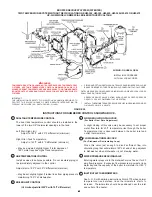
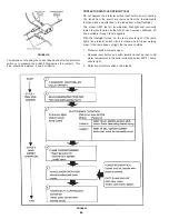
At the time of removal of an existing boiler, the following steps shall
be followed with each appliance remaining connected to the
common venting system placed in operation, while the other
appliances remaining connected to the common venting system
are not in operation.

Seal any unused openings in the common venting system.

Visually inspect the venting system for proper size and horizontal
pitch and determine there is no blockage or restriction, leakage,
corrosion and other deficiencies which could cause an unsafe
condition.

Insofar as is practical, close all building doors and windows and
all doors between the space in which the appliances remaining
connected to the common venting system are located and other
spaces of the building. Turn on clothes dryers and any appliance
not connected to the common venting system. Turn on any exhaust
fans, such as range hoods and bathroom exhausts, so they will
operate at maximum speed. Do not operate a summer exhaust
fan. Close fireplace dampers.

Place in operation the appliance being inspected. Follow the
lighting instructions. Adjust thermostat so appliance will operate
continuously.

Test for spillage at the draft hood relief opening after 5 minutes of
main burner operation. Use the flame of a match or candle, or
smoke from a cigarette, cigar or pipe.

After it has been determined that each appliance remaining
connected to the common venting system properly vents when
tested as outlined above, return doors, windows, exhaust fans,
fireplace dampers and any other gas-burning appliance to their
previous condition of use.

Any improper operation of the common venting system should be
corrected so the installation conforms with the National Fuel Gas
Code, ANSI Z223.1 and/or CAN/CGA B149, Installation Codes.
When resizing any portion of the common venting system, the
common venting system should be resized to approach the
minimum size as determined using the appropriate tables in
Appendix F in the National Fuel Gas Code, ANSI Z223.1 and/or
CAN/CGA B149 Installation Codes.

REMOVAL OF EXISTING BOILER FROM A COMMON VENTING SYSTEM

Summary of Contents for Burkay HW-300

Page 1: ...ONTAINS INFORMATION RELATIVE TO YOUR SAFETY PLEASE READ THOROUGHLY BEFORE USING APPLIANCE WARNING If the information in this manual is not followed exactly a fire or explosion may result causing prope...

Page 2: ...1451 68 5 16 1735 67 1702 64 3 4 1645 B Height to top of jacket 43 1 4 1099 45 1 8 1146 45 1 8 1146 56 1 4 1429 56 1 4 1429 56 1 4 1429 C Floor to center line water inlet 36 914 38 3 4 984 38 3 4 984...

Page 3: ...831 1 627 1 464 1 331 1 220 1 127 1 046 GPH 1 935 1 290 967 774 645 553 484 430 387 352 322 298 276 HW 420 420 000 LPH 7 708 5 138 3 854 3 083 2 569 2 202 1 927 1 713 1 542 1 401 1 285 1 186 1 101 GPH...

Page 4: ...MMON VENTINGSYSTEM 54 GENERALMAINTENANCE 55 Relief Valve 55 CLEANINGANDFLUSHINGINSTRUCTIONS 55 Internal Contaminants 55 Hot Water Supply Boilers Preventive Maintenance 55 Deliming 55 56 Deliming Solve...

Page 5: ...OF AIR WILL CAUSE RECIRCULATION OF COMBUSTION PRODUCTS RESULTING IN AIR CONTAMINATION THAT MAY BE HAZARDOUS TO LIFE SUCH A CONDITION OFTEN WILL RESULT IN A YELLOW LUMINOUS BURNER FLAME CAUSING CARBONI...

Page 6: ...y uncontaminated air should be obtained from remote or outside sources INSTALLATION CLEARANCES These boilers are approved for installation on combustible flooring in an alcove with minimum clearance t...

Page 7: ...w Installations A O Smith LINEAR TEMP systems have been designed to provide efficient trouble free operation of the boiler sizes covered in this manual with any of the following conditions a Unknown s...

Page 8: ...stallation is an excellent way to modernize the system The A O Smith boiler s should be installed on a pipe loop with a separate circulating pump selected from PUMPAND PIPE SIZING DATATABLE Figure 3 s...

Page 9: ...PIPINGISOLATION OFTHEBOILERFROMTHECHILLER FIGURE4 If the boiler is connected to chilled water piping or its heating coils are exposed to refrigerated air the boiler piping system must be equipped with...

Page 10: ...ched to the piping system When table 6 is to be used to select the piping size calculate the gas demand in terms of cubic feet per hour for each piping system outlet The gas demand for an appliance ca...

Page 11: ...ith a cubic foot per hour demand of 2 060 and with 50 lineal feet of gas supply line table 6 shows a pipe size of 3 76mm is required NOTE For other than 60 specific gravity apply multiplier factor as...

Page 12: ...or chimney must be a minimum height of 12 305mm above the annual snow fall to prevent blockage Building materials must not come in contact with combustion products from stack or chimney due to the de...

Page 13: ...NAND UNSAFE CONDITIONS Vent connectors serving appliances vented by natural draft shall not be connected into any portion of mechanical draft systems operating under positive pressure 3 CONNECTING BOI...

Page 14: ...12 12 12 12 12 12 12 2 12 12 12 10 10 10 10 10 10 3 12 10 10 10 10 10 10 10 10 4 or more 10 10 10 10 10 10 10 10 10 Number Total Total Vent Height Measured in Feet Above Draft Hood if Units Input 10...

Page 15: ...he combustion products are going up the chimney or gas vent properly by passing a lighted match or taper around the edge of the relief opening of the draft hood If the chimney or gas vent is drawing p...

Page 16: ...L REGULATIONS The boiler when installed must be electrically bonded to ground in accordance with the requirements of the authority having jurisdiction or in the absence of such requirements with the N...

Page 17: ...ECTIONDIAGRAM HWB HW 300 399 420 500 610 NATURALGAS SINGLESTAGEI I D ROBERTSHAW GASVALVE HWB HW 300 399 420 520 610 NATURAL GAS ONLY CANADIAN MODELS FIGURE10 Robertshaw is a registered trademark of Fu...

Page 18: ...18 18 18 18 18 CONNECTIONDIAGRAM HWB HW 420 520 610 PROPANEGAS SINGLESTAGEPROPANE ROBERTSHAWGASVALVE 24 VOLT HW HWB 420 520 610 CANADIAN MODELS FIGURE11...

Page 19: ...19 19 19 19 19 SINGLESTAGEPROPANEROBERTSHAWGASVALVE 24 VOLT HWB HW 300 399 CANADIAN MODELS FIGURE11A CONNECTION DIAGRAM HWB HW 300 399 PROPANEGAS FIGURE13...

Page 20: ...20 20 20 20 20 HW 300 HW 399 HW 420 HW 500 HW 670 NATURALGAS SINGLESTAGEI I D ROBERTSHAWGASVALVE HW 300 399 420 520 670 NATURAL GAS ONLY U S MODELS FIGURE11B...

Page 21: ...21 21 21 21 21 HW 300 HW 399 HW 420 HW 500 HW 670 PROPANEGAS FIGURE12 SINGLESTAGEI I D ROBERTSHAWGASVALVE HW 300 399 420 520 670 PROPANE GAS ONLY U S MODELS FIGURE11C...

Page 22: ...emperature thermostats A single bulb outdoor sensing control will prevent overheating of halls stairways or other uncontrolled areas There are occasions when outdoor temperatures are temporarily too w...

Page 23: ...IAGRAM TWO BOILER LINEAR TEMP INSTALLATION WITH TWO CIRCULATORS FIGURE13 CONTROLAPPLICATIONDIAGRAM THREEBOILERLINEAR TEMP INSTALLATIONWITHTHREECIRCULATORS FIGURE14 NOTE 1 Building temperature controls...

Page 24: ...ATION WITH TWO CIRCULATORS FIGURE15 NOTE 1 Building temperature controls supply electric power to building circulator 2 Main flow switch proves main water flow before energizing sequencing and resetti...

Page 25: ...UNIT INSTALLATION FOR HOT WATER SUPPLY APPLICATION CANADIAN MODELS JUNCTION BOX W 6 TERMINALS FIGURE 17 FIGURE 19 CER TEMP 80 1 UNIT INSTALLATION FOR HOT WATER SUPPLY APPLICATION U S MODELS JUCNTION...

Page 26: ...26 26 26 26 26 CER TEMP 80 2 OR 3 UNIT INSTALLATION FOR HOT WATER SUPPLY APPLICATION CANADIAN MODELS JUNCTION BOX W 6 TERMINALS FIGURE 20...

Page 27: ...27 27 27 27 27 FIGURE 21 SCHEMATIC CANADIAN MODELS JUNCTION BOX W 6 TERMINALS...

Page 28: ...28 28 28 28 28 CER TEMP 80 2 OR 3 UNIT INSTALLATION CONNECTION DIAGRAM FOR HOT WATER SUPPLY APPLICATION U S MODELS JUNCTION BOX W 4 TERMINALS FIGURE 22...

Page 29: ...29 29 29 29 29 CER TEMP 80 2 OR 3 UNIT INSTALLATION SCHEMATIC DIAGRAM FOR HOT WATER SUPPLY APPLICATION U S MODELS JUNCTION BOX W 4 TERMINALS FIGURE 23...

Page 30: ...30 30 FIGURE 24 BOOSTER RECOVERY WIRING DIAGRAM CANADIAN MODELS JUNCTION BOX W 6 TERMINALS SHURE TEMP BOOSTER RECOVERY WIRING DIAGRAM TWO TEMPERATURE SYSTEM CANADIAN MODELS JUNCTION BOX W 6 TERMINALS...

Page 31: ...1 31 31 31 BOOSTER RECOVERY WIRING DIAGRAM U S MODELS JUNCTION BOX W 4 TERMINALS FIGURE 26 SHURE TEMP BOOSTER RECOVERY WIRING DIAGRAM TWO TEMPERATURE SYSTEM U S MODELS JUNCTION BOX W 4 TERMINALS FIGUR...

Page 32: ...nt is recommended This will protect the dishwashers coffee urns water boilers water piping and other equipment When water softening or water treatment is not practical a comparatively easy method of p...

Page 33: ...as shown in the installation diagrams Thermometers are installed in the system as a means of detecting a possible liming condition in the boiler An increase of 3 C 5 F over the normal temperature rise...

Page 34: ...ON HW 520 HW 610 HW 670 WIRING FIGURES 17 18 19 INSTALLINACCORDANCE WITH ALL LOCAL CODES ONE HW 300 HW 399 HW 420 HW 520 HW 610 OR ONE HW 670 UP FLOW MODEL COMMERCIALBOILERWITHVERTICALTANK USETHISTAB...

Page 35: ...EIR USAGE PRESSURE RELIEF VALVE RATING SHOULD NOT EXCEED PRESSURE CAPACITY OF ANY COMPONENT IN THE SYSTEM INSTALL THERMOMETER AND PRESSURE RELIEF IN OPENINGS PROVIDED ON HW 520 HW 610 HW 670 USETHISTA...

Page 36: ...F ANY COMPONENT IN THE SYSTEM INSTALL THERMOMETER AND PRESSURE RELIEF IN OPENINGS PROVIDED ON HW 520 HW 610 HW 670 WIRING FIGURES 20 21 22 OR 23 HEATERS SPACED 30 APART INSTALLINACCORDANCE WITH ALL LO...

Page 37: ...ED PRESSURE CAPACITY OF ANY COMPONENT IN THE SYSTEM INSTALL THERMOMETER AND PRESSURE RELIEF IN OPENINGS PROVIDED ON HW 520 HW 610 HW 670 WIRING FIGURES 20 21 22 or 23 INSTALLINACCORDANCE WITH ALL LOCA...

Page 38: ...SHOULD NOT EXCEED PRESSURE CAPACITY OF ANY COMPONENT IN THE SYSTEM INSTALLTHERMOMETER AND PRESSURE RELIEF IN OPENINGS PROVIDED ON HW 520 HW 610 HW 670 FIGURE 33 USETHISTABLEFORCORRECT PUMPAND WATER PI...

Page 39: ...EXCEED PRESSURE CAPACITY OF ANY COMPONENT IN THE SYSTEM INSTALLTHERMOMETERAND PRESSURE RELIEF IN OPENINGS PROVIDED ON HW 520 HW 610 HW 670 WIRING FIGURES 20 21 22 OR 23 HEATERS SPACED 24 APART INSTAL...

Page 40: ...F IN OPENINGS PROVIDED ON HW 520 HW 610 HW 670 IMPORTANT THE INSTALLATION OF SAFETY FLOW SWITCH AS SHOWN IS REQUIRED TO PROTECT THE BOILER IN CASE OF WATER SERVICE INTERRUPTION OR CIRCULATOR FAILURE A...

Page 41: ...E BOOSTER OUTPUT ADD ANANTI SCALD VALVE FOR HOT WATER SUPPLIED TO FIXTURES USETHISTABLEFORCORRECT PUMPAND WATER PIPE SIZE Minimum B G Armstrong Model Pipe Size Pump Pump Number Inches Size Size HW 300...

Page 42: ...STALLATION OF SAFETY FLOW SWITCH AS SHOWN IS REQUIRED TO PROTECT THE BOILER IN CASE OF WATER SERVICE INTERRUPTION OR CIRCULATOR FAILURE A O SMITH PKG NO 211480 WIRING FIGURE 24 OR 26 INSTALLINACCORDAN...

Page 43: ...160 F with 20 F differential minimum Right Dial Tank Temperature Adjust to 140 F with 8 F differential minimum May be adjusted slightly higher if total demand of 180 F water requires higher tank tempe...

Page 44: ...TANKS DANGER TEMPERATURE SETTING SHOULD NOT EXCEED SAFE USE TEMPERATURE AT FIXTURES SEE TANK TEMPERATURE CONTROL WARNING ON PAGE 32 IF HIGHER PREHEATTEMPERATURESARENECESSARYTO OBTAIN ADEQUATE BOOSTER...

Page 45: ...ng causing a call for heat and allowing unit to run until High Limit Temperature Control trips 3 Resetting the High Limit Temperature Control to a higher setting unit should run 4 Reset System Control...

Page 46: ...ics are not evident check for accumulation of lint or other foreign material that restricts or blocks the air openings to the burner or boiler Also check for good flow of combustion and ventilating ai...

Page 47: ...OUR GAS SUPPLIER FROM A NEIGHBOR S PHONE FOLLOW THE GAS SUPPLIER S INSTRUCTIONS IF YOU CANNOT REACH YOUR GAS SUPPLIER CALL THEFIREDEPARTMENT C USE ONLY YOUR HAND TO PUSH IN OR TURN THE GAS CONTROL KNO...

Page 48: ...UCH ANY ELECTRIC SWITCH DO NOT USE ANY PHONE IN YOUR BUILDING IMMEDIATELY CALL YOUR GAS SUPPLIER FROM A NEIGHBOR S PHONE FOLLOW THE GAS SUPPLIER S INSTRUCTIONS IF YOU CANNOT REACH YOUR GAS SUPPLIER CA...

Page 49: ...ot gas adjustment located in the gas valve The pilot flame should envelop 3 8 to 1 2 inch of the tip of the thermocouple Remove pilot adjustment cover screw fig 43b Turn inner adjustment screw or pilo...

Page 50: ...eads from a test flashlight The model N22T test kit combination flashlight and continuity tester is manufactured by the RAY O Vac Company Madison WI and available through local suppliers With the flas...

Page 51: ...S SECONDS Type Value HWB HWB HWB HWB HWB HWB Gas Btu Ft 3 HW 300 HW 399 HW 420 HW 520 HW 610 HW 670 Natural 1050 12 6 9 5 9 0 7 3 6 2 5 7 Propane 2500 30 0 22 6 21 4 17 3 14 8 13 4 IMPORTANT UNDER NO...

Page 52: ...e check the rating plate before making changes The input reduction is primarily achieved by reducing the size of the main burner orifices To do this the main burner orifices require replacement with o...

Page 53: ...2 x 1 1 2 x 1 tee for a 1 1 2 pipe application For larger pipe sizes use a reducing tee in order to keep the switch as close to the pipe as possible Install the flow switch in the branch top opening...

Page 54: ...rdered through A O Smith dealers authorized servicers or distributors Refer to the Yellow Pages for where to call or contact the A O Smith Enterprises Ltd P O Box 310 768 Erie St Stratford Ontario N5A...

Page 55: ...at may have accumulated during installation This is doubly important when a replacement boiler is installed into an existing system where Stop Leak or other boiler additives have been used Failure to...

Page 56: ...inue to fill until foaming action stops 9 When foaming action has stopped completely allow 10 to 15 minutes for the solvent to dissolve any remaining scale in the unit 10 Open the drain cock and drain...

Page 57: ...wiring Repair or defective replace valve Circulating pump Power off or system Check power supply and burner off wiring is incorrect and wiring Tank temperature control Replace thermostat defective Bur...

Page 58: ...s the ceramic insulator surrounding the electrode cracked or broken Replace pilot burner assembly Replace ignition module Turn on gas supply turn on power supply Securely connect cable and or ground w...

Page 59: ...e firmly attached to pilot assembly and GND terminal on module Are ignition cable and ground wire in good condition not brittle burnt or cracked Ensure ground strap is the closest metal to the igniter...

Page 60: ...he igniter sensor rod in good condition not broken or cracked Is the igniter sensor rod in good condition not worn corroded sooted or damaged Replace ignition module Correct the situation by consultin...

Page 61: ...pilot ground wire firmly attached to the pilot assembly and GND terminal on module Are high voltage cable and ground wire in good condition not brittle burnt or cracked Make sure pilot flame spreader...

Page 62: ...dministrative charges for forwarding the replacement part from the nearest distributor and returning the claimed defective part to such distributor c All cost necessary or incidental for any materials...

Page 63: ...63 63 63 63 63...

Page 64: ...64 64 64 64 64 5621 W 115TH STREET ALSIP IL 60803 PHONE 1 800 433 2545 FAX 1 800 433 2515 E MAIL parts hotwater com www hotwater com REPLACEMENT PARTS...

Reviews: