background image


305, 505, 705 Indoor Manual 

39 

Warranty 

What is not covered? 

This Warranty does not cover any failures or operating difficulties due to the following: 

• 

accident, abuse, or misuse 

• 

alteration 

• 

misapplication 

• 

force majeure 

• 

improper installation (such as but not limited to inadequate water quality, condensate damage,  improper 
venting, incorrect gas type, incorrect gas or water pressure, or absence of a drain pan under the appliance) 

• 

improper maintenance (such as but not limited to scale buildup, freeze damage, or vent blockage) 

• 

incorrect sizing 

• 

any other causes other than defects in materials or workmanship 

 
This Warranty does not apply to any product whose serial number or manufacture date has been defaced.  This 
Warranty does not cover any product used in an application that uses chemically treated water such as a pool or 
spa heater.  This appliance is suitable for filling large or whirlpool bath tubs with potable water.  Refer to the Water 
Quality Section in the Operation and Installation Manual. 

No one is authorized to make any other warranties on behalf of the manufacturer. Except as expressly provided 
herein, there are no other warranties, expressed or implied, including, but not limited to warranties of 
merchantability or fitness for a particular purpose, which extend beyond the description of the warranty herein and 
further the manufacturer shall not be liable for indirect, incidental, special, consequential or other similar damages 
that may arise, including lost profits, damage to person or property, loss of use, inconvenience, or liability arising 
from improper installation, service or use.  Some states do not allow the exclusion or limitation of incidental or 
consequential damages, so the above limitation may not apply to you. 

Limitation on implied warranties 

Any implied warranties of merchantability and fitness arising under state law are limited in duration to the period of 
coverage provided by this limited Warranty, unless the period provided by state law is less.  Some states do not 
allow limitations on how long an implied Warranty lasts, so the above limitation may not apply to you. 

This Warranty gives you specific legal rights, and you may also have other rights which vary from state to state.


Summary of Contents for 505

Page 1: ...n and service must be performed by a qualified installer service agency or the gas supplier WARNING If the information in these instructions is not followed exactly a fire or explosion may result caus...

Page 2: ...Water Heater 14 Electrical Connection 15 Gas Piping General Instructions 15 Pipe Sizing Procedure Example 16 Water Piping General Instructions 17 Pressure Relief Valve 17 Freeze Protection 17 Freeze P...

Page 3: ...5 C Maximum Temp Setting Residential 140 F 60 C Minimum Temperature Setting 98 F 37 C Weight 50 lb 23 kg 55 lb 25 kg Efficiency Rating Propane Gas 84 Noise level 49 dB Electrical Consumption Normal 79...

Page 4: ...is symbol alerts you to potential hazards that can kill or hurt you and others Indicates an imminently hazardous situation which if not avoided will result in death or serious injury Indicates a poten...

Page 5: ...water is constantly monitored This appliance may adjust the water flow in order to maintain the temperature setting The water flow may vary from summer to winter due to the difference in ground water...

Page 6: ...re setting for this appliance installed without a remote controller is 120 F 49 C If desired the temperature setting can be changed to 140 F 60 C by adjustment of a dip switch Set dip switch 5 to ON t...

Page 7: ...suggestions only A temperature lower than 98 F 37 C can be obtained at the tap by mixing with cold water To change the temperature scale from Celsius to Fahrenheit or vice versa press and hold the On...

Page 8: ...to wipe cabinet Vent System The vent system should be inspected at least annually for blockages or damage Motors Motors are permanently lubricated and do not need periodic lubrication Keep fan and mo...

Page 9: ...ck gas solenoid valves for open or short circuits Remove burner cover and ensure all burners are properly seated Remove burner plate and inspect burner surface for condensation or debris 12 Flame Fail...

Page 10: ...build up Ensure fan blade is tight on motor shaft and is in good condition Replace sensor 52 Modulating Solenoid Valve Signal Abnormal Check modulating gas solenoid valve wiring harness for loose or...

Page 11: ...ter heater continues to run The fan is designed to continue running for a short time after the flow of water stops This is to ensure constant water temperatures during rapid starting and stopping as w...

Page 12: ...ter and cold water lines V3 and V4 3 Connect pump outlet hose H1 to the cold water line at service valve V2 4 Connect drain hose H3 to service valve V1 5 Pour approximately 4 gallons of virgin food gr...

Page 13: ...pressures in excess of 1 2 psi 3 5 kPa 13 84 in W C The appliance must be isolated from the gas supply piping system by closing its individual manual shutoff valve during any pressure testing of the...

Page 14: ...Non Combustibles 305 505 705 305 505 705 Top of Heater 6 inches 152 mm 12 inches 305 mm 2 inches 51 mm 2 inches 51 mm Back of Heater 0 zero 0 zero 0 zero 0 zero Front of Heater 6 inches 152 mm 24 inch...

Page 15: ...oap and water or an equivalent nonflammable solution as applicable Since some leak test solutions including soap and water may cause corrosion or stress cracking the piping shall be rinsed with water...

Page 16: ...opane Gas Pipe Size inches 3 4 1 1 1 4 1 1 2 10 273 514 1060 1580 20 188 353 726 1090 30 151 284 583 873 40 129 243 499 747 50 114 215 442 662 60 104 195 400 600 70 95 179 368 552 80 89 167 343 514 90...

Page 17: ...le water heating appliance Ensure that the water filter on the water heater is clean and installed An approved pressure relief valve is required by the American National Standard ANSI Z21 10 3 Canadia...

Page 18: ...mpliance with local building code requirements It is the responsibility of the contractor engineer to ensure installation is in accordance with all local building codes Confer with local building offi...

Page 19: ...ain Valve KEY This is not an engineered drawing It is intended only as a guide and not as a replacement for professionally engineered project drawings This drawing is not intended to describe a comple...

Page 20: ...is not an engineered drawing It is intended only as a guide and not as a replacement for professionally engineered project drawings This drawing is not intended to describe a complete system It is up...

Page 21: ...turn plumbing Pump to be of bronze or stainless construc tion This is not an engineered drawing It is intended only as a guide and not as a replacement for professionally engineered project drawings T...

Page 22: ...pipe fittings Avoid dips or sags in horizontal vent runs by installing supports per the vent manufacturer s instructions Support horizontal vent runs every four feet and all vertical vent runs every s...

Page 23: ...es the water heater will run properly Blocked flue error codes and shutdowns may result if dip switch no 1 is not in the correct position On the 305 and 505 models the maximum water flow capacity will...

Page 24: ...NA ProTech Systems FasNSeal FSAAU4 FSRC4 FSBS4 FSDVPTB04LH FSDVWT4 Metal Fab Corr Guard 4CGOA 4CGSWC 4CGSWMCM 4CG7HT90 4CG7HT Venting Products Vent Manufacturer Contact Information for Installation I...

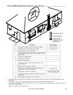
Page 25: ...Description US Installations A Clearance above grade veranda porch deck or balcony 12 inches 30 cm B Clearance to window or door that may be opened 12 inches 30 cm C Clearance to permanently closed wi...

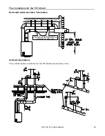
Page 26: ...ater heater terminals at different levels 12 12 36 INSIDE CORNER V V 0 91 m to ventilated or unventilated soffit or eve vent or to a deck or porch 0 30 m to an inside corner 0 30 m between water heate...

Page 27: ...5 Install the 4 screws at the vent top and tighten the 4 screws at the bracket Secure the first vent component to the water heater with one self tapping screw at the hole located above the condensate...

Page 28: ...screws attach the pipe to the air intake terminal 5 Apply a bead of silicone around the pipe and air intake terminal ensuring an air tight connection Exhaust Pipe Assembly Refer to the manufacturer s...

Page 29: ...erminations The air intake requires a return bend or two 90 elbows to prevent entry of rain SLOPE INTAKE AND EXHAUST TOWARD OUTSIDE TERMINATION MINIMUM 1 4 PER FOOT Horizontal with Concentric Terminat...

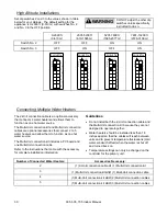
Page 30: ...cable or 1 Multi Unit connection kit 3 1 Multi Unit connection kit and 1 Multi Unit connection cable 4 1 Multi Unit connection kit and 2 Multi Unit connection cables 5 1 Multi Unit connection kit and...

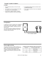
Page 31: ...ld be a non polarized two core cable with a minimum gauge of 22 AWG The maximum cable length from each controller to the water heater depends on the total number of wired controllers connected to the...

Page 32: ...s hole at the base of the unit and connect the wires to the controller terminals on the right hand side bottom of the PCB 11 Secure the controller cable using the clamp provided 12 Replace plastic cov...

Page 33: ...O APPLIANCE 1 Turn off all electric power to the appliance using the ON OFF button 2 Set the thermostat to lowest setting 3 Locate the manual gas valve on the side of the heater Turn the manual valve...

Page 34: ...ow Data Water Flow gpm delta T Temperature Rise F 0 5 10 15 20 25 30 35 40 45 0 2 4 6 8 10 12 0 10 20 30 40 50 60 70 80 90 100 505 305 Pressure Loss ft head Pressure Loss psi Water Flow gpm 705 0 0 1...

Page 35: ...system and any additional plumbing pressure losses The pressure drop curve based on the water heater model is provided in this manual Replacement When replacing an existing space heating application...

Page 36: ...Height Unit 22 9 582 23 6 600 D Height with brackets 25 5 648 2 25 2 639 8 E Hot Water Outlet from wall 3 6 91 4 3 110 F Hot Water Outlet from center 4 3 110 2 4 61 G Cold Water Inlet from wall 2 8 7...

Page 37: ...DC5V A B C SG SWITCHING POWERSUPPLY THERMISTOR CIRCUIT B SG RELAY 1 A WATERFLOW SENSOR CIRCUIT WATERFLOW CONTROLDEVICE CIRCUIT A SG A SG SG A QS SG FR FLAME DETECTING CIRCUIT FLAMEROD GND SG A REMOTE...

Page 38: ...ed as on demand What will be done Repair or replacement of the covered product or any part or component that is defective in materials or workmanship as set forth as follows Payment of reasonable labo...

Page 39: ...thorized to make any other warranties on behalf of the manufacturer Except as expressly provided herein there are no other warranties expressed or implied including but not limited to warranties of me...

Page 40: ......

Reviews: