background image

INTRODUCTION

SAFETY

Read This Manual Thoroughly

The manufacturer cannot possibly anticipate every possible circumstance that might involve a hazard. The 
warnings in this manual and the tags and decals affixed to the unit are therefore not all-inclusive. If you use a 
procedure, work method or operating technique that the manufacturer does not specifically recommend you 
must satisfy yourself that it is safe for you and others. You must also make sure that the procedure work 
method or operating technique that you choose does not render the generator unsafe.

If any section of this manual is not understood, 
contact customer Service at 855-888-3598, or 
www.a-ipower.com for starting, operating and 
servicing procedures. The owner is responsible for 
proper maintenance and safe use of the unit.
SAVE THESE INSTRUCTIONS for future reference. 
This manual contains important instructions that 
must be followed during placement, operation and 
maintenance of the unit and its components. Always 
supply this manual to any individual that will use this 
unit.

The information in this manual is accurate based on 
products produced at the time of publication. The 
manufacturer reserves the right to make technical 
updates, corrections and product revisions at any 
time without notice.

1

Definitions And Symbols

DANGER

Indicates a hazard
which, if not avoided,
will result in death or
serious injury.

WARNING

Indicates a hazard
which, if not avoided,
could result in death
or serious injury.

NOTICE

Indicates information 
considered important, 
but not hazard-related 
(e.g.,messages relating 
to property damage).

CAUTION

Indicates a hazard
which, if not avoided,
could result in minor 
or moderate injury.

WARNING

Read and understand manual completely 
before using product. Failure to 
completely understand manual and 
product couldresult in death or serious 
injury.

WARNING

Operating, servicing, and maintaining this equipment 
can expose you to chemicals including engine 
exhaust, carbon monoxide, phthalates, and lead, 
which are known to the State of California to cause 
cancer and birth defects orother reproductive harm. 
To minimize exposure, avoid breathing exhaust, and 
wear gloves or wash your hands frequently when 
servicing this equipment. For more information go to 
www.P65warnings.ca.gov.

The words DANGER, WARNING, CAUTION, and NOTICE are used throughout this manual to highlight important 
information. Make sure that the meanings of this safety information is known to all who operate, perform 
maintenance on, or are nearthe generator.

This safety alert symbol appears with most safety statements. It means attention,become alert, your 
safety is involved! Please read and abide by the message that follows the safety alerts symbol.

Summary of Contents for PK12000

Page 1: ...Parallel Kit Owner s Manual P N 32082 04884 00 Model Serial Date Purchased Model PK12000 REV00 SAVE THIS MANUAL FOR FUTURE REFERENCE DO NOT RETURN TO STORE CALL US FIRST 855 888 3598 FOR SUPPORT ...

Page 2: ...roduction 1 Read This Manual Thoroughly 1 Safety 1 Definitions And Symbols 1 Assembly And Operation 3 Set up and Operation 3 Controls And Feature 5 Parts Diagram And Parts List 6 Circuit Diagram 7 Warranty 8 Parts Diagram 6 ...

Page 3: ...y time without notice 1 Definitions And Symbols DANGER Indicates a hazard which if not avoided will result in death or serious injury WARNING Indicates a hazard which if not avoided could result in death or serious injury NOTICE Indicates information considered important but not hazard related e g messages relating to property damage CAUTION Indicates a hazard which if not avoided could result in ...

Page 4: ...isconnect parallel kit while generator is running Doing so can cause permanent damage not covered under warranty 8 Do not get the product wet Do not use if this product is exposed to moisture 9 If required use only certified approved extension cords with this product 10 Do not overload the parallel kit The kit can supply a maximum of 50 Amps at 240 Volt or 12000 Watts per outlets depending on the ...

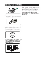
Page 5: ... ON or OFF on both generators 4 On each inverter 4 1 Remove the parallel outlet covers Plug the black and red parallel cable terminals to the black and red parallel outlet black to black and red to red on each corresponding inverters control panel Do not plug two red cables or two black cables into the same inverter 4 2 Loosen nuts on grounding terminals and attach round wire to ground terminal in...

Page 6: ...Allow generator output to stabilize before plugging in the next load NOTE It is strongly recommended to plug in devices with the largest output first and the smallest output last to help prevent overloading the inverters Do not exceed maximum wattage rating of inverters parallel kit and receptacles 8 When finished turn off the inverter generators per owner s manual instructions and then disconnect...

Page 7: ... 2 4 8 1 4 3 5 2 6 7 8 1 3 1 Grouding Wire 2 Parallel Kit 3 Parallel Cable Terminal 4 Parallel Cable GEN 2 5 240V AC 50A 14 50R 6 Circuit Breakers 7 240V AC 30A L6 30R 8 Parallel Cable GEN 1 9 Parallel Outlets 10 Grouding Wire 9 3 10 ...

Page 8: ...2 2 Part Number Description Outlet cover L6 30R Outlet cover 14 50R Cross plate head bolt Cross plate head bolt Parallel box panel Receptacle L6 30R Receptacle 14 50R Circuit breaker amp 50A Circuit breaker amp 30A Hex nut Back cover Rubber cover Parallel cable 70001 00965 00 3 1 2 4 5 6 7 12 13 8 9 10 11 ...

Page 9: ...gram 50A 30A 50A 14 50R 30A L6 30R R Y G L N G B L N G CIRCUIT DIAGRAM Model PK12000 7 B BLACK Br BROWN G GREEN Gy GRAY L BLUE O ORANGE R RED W WHITE Y YELLOW P PINK B W BLACK WHITE Y G YELLOW GREEN R W RED WHITE ...

Page 10: ...ver repair when normal use has exhausted the lifetime of a part s or engine Installation and Maintenance this warranty does not cover improper or unauthorized assembly alteration modification or any other damage resulting from misuse or neglect Normal maintenance parts this warranty does not cover spark plugs air filters adjustments or other related service due to obstructions and other build ups ...

Page 11: ...ackaging Improperly packaged returns will not be accepted Must have adequate packing for transportation Federal Law requires that all machines that utilize gasoline oil or other flammable liquids must be drained Completely Thoroughly prior to shipment Gas caps and oil plugs must be left off for 24 hours prior to shipping Please note liability for this violation of the law resides with the sender o...

Page 12: ... 1 Product Value for Price Paid Performance Features Product Appearance Warranty Ease of Maintenance Noise Level 5 HOW LIKELY ARE YOU TO RECOMMEND A iPOWER TO FAMILY OR FRIENDS Extremely Not Likely Likely at all 5 4 3 2 1 Privacy Statement A ipower is committed to respecting your privacy and to complying with the regulations regarding the protection of personal data The survey data we collect is f...

Page 13: ...Fontana CA 92337 USA Phone 855 888 3598 support a ipower com www a ipower com ...

Page 14: ...nual Del Usuario P N 32082 04884 00 Modelo PK12000 REV00 Modelo Número de Serie Fecha de Compra INO LO DEVUELVA A LA TIENDA LLÁMENOS PRIMERO AL 855 888 3598 PARA PEDIR APOYO GUARDE ESTE MANUAL PARA FUTURAS REFERENCIAS ...

Page 15: ...a Este Manual Cuidadosamente 1 Seguridad 1 Definiciones y Símbolos 1 Montaje Y Funcionamiento 3 Configuración y Funcionamiento 3 Controles Y Funciones 5 Dibujos Y listas de Piezas 6 Diagrama Del Circuito 7 Garantía 8 Dibujo de Piezas 6 1 ...

Page 16: ...cualquier momento sin previo aviso DEFINICIONES Y SÍMBOLOS PELIGRO indica un peligro que si no se evita resultará en la muerte o graves lesiones ADVERTENCIA Indica un peligro que si no se evita podría resultar en la muerte o graves lesiones PRECAUCIÓN Indicates a hazard which if not avoided could result in minor or moderate injury ADVERTENCIA Lea y entienda el manual por completo antes de utilizar...

Page 17: ... no conecte ni desconecte el kit paralelo Esto puede causar daños permanentes fuera del alcance de la garantía 8 No humedezca el producto No utilice este producto si está expuesto a la humedad 9 Si es necesario este producto sólo puede utilizar cables de extensión certificados 10 No sobrecargar el kit paralelo Dependiendo de la calificación del generador inversor el kit puede proporcionar hasta 50...

Page 18: ...ctrico Gire y mantenga el interruptor de arranque parada del motor durante 5 segundos hasta que el motor arranque Terminal de cable paralelo Socket paralelo Cable de tierra Si no hay separación el calor residual de un disposi tivo puede decolorar o derretir el plástico de otro 2 Antes de instalar el kit paralelo apague el inversor y conecte todas las cargas eléctricas NOTA No conecte ni desconecte...

Page 19: ...iente carga mantenga la salida del generador estable NOTA Se recomienda encarecidamente insertar prime ro el dispositivo con la salida máxima y luego el dispos itivo con la salida mínima para ayudar a prevenir la sobrecarga del inversor No supere la Potencia máxima del inversor el kit paralelo y el enchufe 8 Cuando haya terminado apague el generador del inversor de acuerdo con las instrucciones de...

Page 20: ...ing 2 Kit Paralelo 3 Terminal de Cable Paralelo 4 Cable Paralelo GEN 2 5 240V AC 50A 14 50R 6 Disyuntores 7 240V AC 30A L6 30R 8 Cable Paralelo GEN 1 9 Puntos de Venta Paralelos 10 Alambre Grouding GEN 1 GEN 2 4 8 1 4 3 5 2 6 7 8 1 3 9 3 10 ...

Page 21: ...cripción Tapa de salida L6 30R Tapa de salida 14 50R Perno de cabeza de placa cruzada Perno de cabeza de placa cruzada Panel de caja paralelo Receptáculo L6 30R Receptáculo 14 50R Disyuntor amperio 50A Disyuntor amperio 30A Tuerca hexagonal Contraportada Cubierta de goma Cable paralelo 70001 00965 00 3 1 2 4 5 6 7 12 13 8 9 10 11 ...

Page 22: ...0A 30A 50A 14 50R 30A L6 30R R Y G L N G B L N G DIAGRAMA DEL CIRCUITO Modelo PK12000 7 B NEGRO Br MARRÓN G VERDE Gy GRIS L AZUL O NARANJA R ROSA W MBLANCO Y AMARILLO P ROSA B W NEGRO BLANCO Y G AMARILLO VERDE R W ROJO BLANCO ...

Page 23: ...s con el producto ayudará a resolver los problemas y enviará todas las piezas de recambio según sea necesario sin costo mientras que el producto está dentro del período de garantía Si no se puede resolver el problema el Departamento de Servicio al Cliente de A iPower a su discreción determinará y autorizará el diagnóstico y reparación a través de uno de sus Centros de Servicio autorizados A iPower...

Page 24: ...vío Las tapas de gas y los tapones de aceite deben dejarse durante 24 horas previo al envío Tenga en cuenta que la responsabilidad por esta violación de la ley reside en el remitente del envío Devolver a la dirección proporcionada en la autorización de devolución utilizando el servicio de paquetería requerido Los productos devueltos sin autorización no serán aceptados Instalación y Mantenimiento e...

Page 25: ...IENTE Totalmente satisfecho Nada satisfecho 5 4 3 2 1 Valor del producto por precio Pagado Rendimiento Funciones Apariencia del producto Garantía Facilidad de mantenimiento Nivel de ruido 5 CUÁN PROPABLE ES QUE USTED RECOMIENDE A iPOWER A SU FAMILIA O AMIGOS Extremadamente probable Nada probable 5 4 3 2 1 Declaración de Privacidad A ipower se compromete a respetar su privacidad y cumplir con las n...

Page 26: ...Fontana CA 92337 EE UU Teléfono 855 888 3598 support a ipower com www a ipower com ...

Page 27: ...èle Manuel de l utilisateur P N 32082 04884 00 Modèle PK12000 REV00 Modèle En série Date d achat NE PAS RETOURNER RANGER APPELEZ NOUS D ABORD 855 888 3598 POUR LE SOUTIEN CONSERVER CE MANUEL POUR RÉFÉRENCE FUTURE ...

Page 28: ...ez Attentivement Ce Manuel 1 Sécurité 1 Définitions Et Symboles 1 Montage Et Fonctionnement 3 Configuration Et Fonctionnement 3 Contrôles Et Fonctions 5 Dessins Et listes De Pièces 6 Diagrammes De Circuits 7 Garanties 8 Dessins Partiels 6 ...

Page 29: ... manuel avant d utiliser le produit Le fait de ne pas comprendre complètement le manuel et le produit peut entraîner la mort ou des blessures graves AVERTISSEMENT L utilisation l entretien et la maintenance de cet équipement peuvent vous exposer à des produits chimiques notamment les gaz d échappement le monoxyde de carbone les phtalates et le plomb qui sont connus dans l État de Californie pour c...

Page 30: ...t le fonctionnement du générateur ne branchez pas ou ne débranchez pas le kit de connexion parallèle Cela peut causer des dommages permanents en dehors de la garantie 8 Ne pas mouiller le produit Ne pas utiliser si ce produit est exposé à l humidité 9 Si nécessaire n utilisez que des rallonges certifiées pour ce produit 10 Ne surchargez pas le kit parallèle Selon la puissance nominale du générateu...

Page 31: ... ON or OFF 4 Sur chaque onduleur 4 1 Retirer le couvercle de sortie parallèle Insérer les bornes de câble parallèles noir et rouge dans les sorties parallèles noir et rouge noir à noir rouge à rouge de chaque panneau de commande d onduleur correspondant Ne branchez pas deux câbles rouges ou deux câbles noirs dans le même onduleur 4 2 desserrer l écrou du terminal de mise à la terre et connecter le...

Page 32: ...ser avant d insérer la charge suivante NOTES Il est fortement recommandé d insérer d abord le dispositif avec la sortie maximale puis le dispositif avec la sortie minimale afin d éviter la surcharge de l onduleur Ne pas dépasser la puissance nominale maximale de l onduleur du kit de dérivation et de la prise 8 Une fois terminé fermez le générateur d onduleur conformément aux instructions du manuel...

Page 33: ... 2 4 8 1 4 3 5 2 6 7 8 1 3 1 Fil Grouding 2 Kit Parallèle 3 Terminal de Câble Parallèle 4 Câble Parallèle GEN 2 5 240V AC 50A 14 50R 6 Disjoncteurs 7 240V AC 30A L6 30R 8 Câble Parallèle GEN 1 9 Prises Parallèles 10 Fil Grouding 9 3 10 ...

Page 34: ...le de sortie L6 30R Couvercle de sortie 14 50R Boulon de tête de plaque transversale Boulon de tête de plaque transversale Panneau de boîte parallèle Réceptacle L6 30R Réceptacle 14 50R Disjoncteur 50A Disjoncteur 30A Écrou hexagonal Quatrième de couverture Couvercle en caoutchouc Câble parallèle 70001 00965 00 3 1 2 4 5 6 7 12 13 8 9 10 11 ...

Page 35: ...cuits 50A 30A 50A 14 50R 30A L6 30R R Y G L N G B L N G DIAGRAMMES DE CIRCUITS Modèle PK12000 7 B NOIR Br BROWN G VERT Gy GRIS L BLUE O ORANGE R ROUGE W BLANC Y JAUNE P ROSE N B NOIR BLANC Y G JAUNE VERT R W ROUGE BLANC ...

Page 36: ...es batteries etc Elle ne couvre pas les défauts esthétiques tels que les rayures de la peinture les décalcomanies etc Elle ne couvre pas les dommages résultant de l utilisation de pièces non ALe service clientèle d A iPower répondra à toutes les questions relatives au produit aidera à résoudre les problèmes et enverra gratuitement toutes les pièces de rechange nécessaires pendant la période de gar...

Page 37: ...oivent être retournés dans leur emballage original ou équivalent Les retours mal emballés ne seront pas acceptés Doit avoir un emballage adéquat pour le transport La loi fédérale exige que toutes les machines qui utilisent de l essence de l huile ou d autres liquides inflammables soient entièrement vidangées avant d être expédiées Les bouchons de gaz et les bouchons d huile doivent être laissés en...

Page 38: ...atisfait 5 4 3 2 1 é y a p x i r p e l r u o p t i u d o r p u d r u e l a V Performance Caractéristiques Apparence du produit Garantie Facilité d entretien Niveau de bruit 5 Seriez vous prêt à recommander A iPOWER à votre famille ou à vos amis Extrêmement efficace Pas du tout probable 5 4 3 2 1 Déclaration de confidentialité A ipower s engage à respecter votre vie privée et à se conformer à la ré...

Page 39: ......

Page 40: ...Fontana CA 92337 USA Téléphone 855 888 3598 support a ipower com www a ipower com ...

Reviews: