background image

table of contents

introduction

1

about this manual

2

features of your PowerPlate™

2

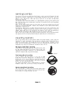
warning and tips

3

mounting locations

3

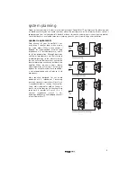
system planning

4

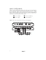
system configurations

5-9

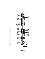
amplifier and crossover controls

10-11

installation

12

controls and connections

12-13

signal sources

14

internal signal routing

15

multi-cross™ crossover and configurations

16

constant bass control

17

AC502 operation

17

tuning

17-18

troubleshooting 

19-20

specifications

21

warranty information

22

introduction

Although it may be hard to remember, back in the 1970’s, car audio as we now know it didn’t really exist.
Sure, music lovers could buy a cassette or 8-track tape deck and some 6" x 9" three-way speakers.
Advanced stereo buffs might even add a "power-booster" to increase output too as much as 12 watts
RMS! But none of this really delivered the power to cut through road noise with sound quality that
compared with the best home audio. Not until 1979 that is, when a/d/s/ introduced the revolutionary
PowerPlate™  P100 amplifier and 300i 2-way plate loudspeakers. Aesthetically, the P100 introduced the
low profile design which has been an a/d/s/ trademark to this day. Technologically, the P100 combined a
high efficiency switching power supply with a state-of-the-art, discrete high-current stereo power
amplifier. For the first time, a car audio system existed with the musical integrity and dynamic range that
made you want to take long drives to nowhere, just to listen to the music. High quality car audio was
born, and the original a/d/s/ PowerPlate™  P100 made it happen.

The latest improvements to the PowerPlate™ line-up include increased heatsink area to facilitate higher
power output, Constant Bass circuit for subwoofer signal that can be mixed into all channels, and fully
balanced high-level inputs compatible with any source. The amplifier you have purchased is an
enhancement of the respected P-series multichannel amplifiers. In this version, we have improved upon
the already acclaimed sound quality by addressing internal details, and upgrading selected components
to incorporate the latest technology which was not available when the P-series was originally designed.
Selected low-noise, high-speed Burr-Brown® op amps are used in critical circuits. Class-A biasing is used
throughout the voltage-gain and active crossover stages. Numerous modifications and "tweaks" were
also performed which improve the power supply dynamics and reduce noise. These changes improve
transparency and dynamic linearity, resulting in a smoother and more detailed top-end, tighter bass, more
explosive dynamic contrasts, and virtually holographic imaging. Left intact are the P-series unequalled
flexibility, high efficiency and superb reliability. These, along with multichannel design, are fundamental in
the a/d/s/ approach to systems engineering, which makes achieving true high fidelity reproduction simple
and predictable in any installation.

1

Summary of Contents for PQ40.2

Page 1: ...analog and digital systems PQ40 2 owner s manual ...

Page 2: ...ntegrity and dynamic range that made you want to take long drives to nowhere just to listen to the music High quality car audio was born and the original a d s PowerPlate P100 made it happen The latest improvements to the PowerPlate line up include increased heatsink area to facilitate higher power output Constant Bass circuit for subwoofer signal that can be mixed into all channels and fully bala...

Page 3: ...voltage fluctuations for reliable performance in the harsh automotive environment Remote Subwoofer or Constant Bass Level Control Capability Can be used with accessory control AC502 to provide a dashboard mounted rear channel subwoofer or Constant Bass level control Digital Crossover Frequency Display The crossover frequency for each channel pair is displayed on the top of the amplifier for quicke...

Page 4: ... have either terminal connected to the speaker frame or to the vehicle chassis mounting locations Due to its low profile there are many possible choices of mounting locations Always mount the PowerPlate in a place that protects it from the elements In addition mount the PowerPlate on a stable flat mounting surface Whenever possible pre drill the mounting holes Remember to check behind the panel fo...

Page 5: ...for subwoofer use and 4 for full range operation Although operation with lower impedances is not likely to cause immediate damage to the internal circuitry the unit will most likely overheat causing the thermal protection circuitry to shut down the amplifier When the chassis cools down normal operation will resume Continuing to operate the amplifier under these conditions is not recommended and wi...

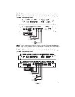
Page 6: ...ding block of a larger more elaborate system Please review systems 1 through 6 described below for suggestions on how to configure the most popular combinations Larger systems may be built from a combination of the simpler building blocks as shown in systems 7 button is disengaged control is non operational button is engaged control is operational System 1 PQ40 2 used in 4 channel mode with front ...

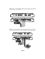
Page 7: ... high pass 2 channels low pass or bandpass Depending on the crossover frequency chosen this configuration may be used for satellite subwoofer operation or to bi amp a midrange tweeter combination as shown Note Although shown as 2 channel the source unit may be either 2 or 4 channel depending on the setting of the 2 4 channel switch 6 front left satellite front right satellite subwoofer 60A front l...

Page 8: ...mode System 5 PQ40 2 used in front high pass rear tri mode operation Channels 1 2 can be configured for high pass or full range operation Rear channel must be configured for full range operation Important Choose passive crossover frequencies for the subwoofer and high pass speakers that do not overlap 7 subwoofer subwoofer 60A front left satellite front right satellite rear right satellite rear le...

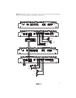
Page 9: ... One amp drives bi amped midranges and tweeters with the second driving rear fill speakers and subwoofers 8 front right midrange front left midrange front right tweeter front left tweeter rear left satellite rear right satellite subwoofer subwoofer 60A 60A ...

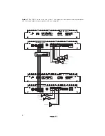
Page 10: ...as in system 2 One amp drives front speakers and one subwoofer with the second amp driving rear speakers and one subwoofer 9 subwoofer front right satellite front left satellite rear left satellite rear right satellite subwoofer 60A 60A ...

Page 11: ...10 amplifier and crossover controls ...

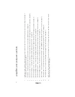
Page 12: ...4 highpass frequency This control sets the highpass crossover point for channels 3 and 4 see page 16 7 crossover 3 4 lowpass switch Push this switch IN to activate the channel 3 4 lowpass crossover or OUT to bypass the crossover see page 16 8 crossover 3 4 lowpass frequency This control sets the lowpass crossover point for channels 3 and 4 see page 16 9 output switches These switches determine whe...

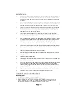
Page 13: ...rmation on the proper connections The speaker terminal blocks install with the set screws facing up and power terminal block installs with the set screws facing down 6 Preset the 2 4 channel selector switch crossover and channel mode switches and crossover frequency switches to the desired positions Refer to the controls and connections section for more information 7 Adjust all amplifier input lev...

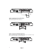
Page 14: ... bridged configurations Minimum recommended impedance is 4 when bridged to subwoofers and 4 when bridged to full range speakers Speaker terminals accept up to AWG 12 speaker wire 13 Connect to 12V turn on lead from source unit Connect to chassis of vehicle Connect to chassis of vehicle 60 Amp fuse less than 18 from battery Factory chassis ground fuse 60A 60A 60A ...

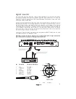
Page 15: ...igh end aftermarket source unit The speaker outputs of the factory radio are simply connected to a mini DIN adapter as shown below From this point on the signal can be treated exactly as you would a preamp level signal except that the input level controls on the PowerPlate will be set to a lower than usual level when you make your final adjustments Conventional aftermarket sources may be connected...

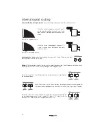
Page 16: ... and 3 4 adjust the input sensitivity from 100 mV to 8 VRMS Output Three position switches determine the output configuration Each stereo pair of channels can be configured in either stereo summed bridged and bridged mono When the switch is in the left position the output channels are configured for stereo operation When the switch is in the center position the output channels are configured for s...

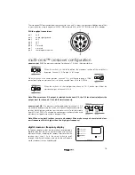
Page 17: ...n crossover 3 4 output is selected for channels 1 2 the 3 4 level control adjusts the output level for channels 1 2 and 3 4 simultaneously xover control 3 4 The crossover sections dedicated for channels 3 4 are activated by depressing the switch next to each frequency adjustment control Both high pass and low pass crossovers are infinitely adjustable from 45Hz to 5 000Hz The high pass and low pass...

Page 18: ... cross crossover section are marked at four reference frequency points These are 45Hz 175Hz 600Hz and 5 000Hz Specific crossover points should be chosen based on the operating range recommended by the manufacturer of your speakers The 85Hz position is a good starting point to use for subwoofer low pass or midrange high pass use When bi amping a d s loudspeaker components 2500Hz is a good starting ...

Page 19: ...more Back down on the volume control slightly until the distortion goes away You have just found the maximum undistorted output level of your source unit Do not exceed the level in normal operation as doing so will just send a distorted signal to the rest of the system 7 Returning to the PowerPlate level control associated with the front main speakers slowly increase it until you reach the point w...

Page 20: ...is proper when amplifier heatsink ventilation for amplifier and temperature exceeds 90 C improve ventilation as needed loose or poor audio input check input connections and repair or replace as needed distorted output amplifier level sensitivity set too reset gain referring to the high exceeding maximum tuning section of the manual output capability of amplifier for detailed instructions impedance...

Page 21: ...e speakers to achieve a higher impedance short in power wire or incorrect check power and ground power connections connections and repair as needed fuse used is smaller than replace with proper fuse size recommended too much current being drawn check speaker impedance load if below 2 stereo or 4 mono rewire speakers to achieve a higher impedance short in power wire or incorrect check power and gro...

Page 22: ...sensitivity 100mV to 8Vrms for full output input impedance 47 k crossover section3 ch 1 2 high pass 12dB octave variable 45Hz 5kHz ch 3 4 high pass low pass 12 dB octave variable 45Hz 5kHz Constant Bass low pass 12dB octave variable 30Hz 300Hz 1 All channels driven continuous FTC rated 4 load 20Hz to 20 000Hz 0 1 THD power input voltage at 13 8DVC 2 All channels driven continuous FTC rated 2 load ...

Page 23: ...r unreasonable use neglect improper service or other causes not arising out of defects in materials or construction ALL WARRANTIES INCLUDING BUT NOT LIMITED TO EXPRESS WARRANTY IMPLIED WARRANTY WARRANTY OF MERCHANTABILITY FITNESS FOR PARTICULAR PURPOSE AND WARRANTY OF NON INFRINGEMENT OF INTELLECTUAL PROPERTY ARE EXPRESSLY EXCLUDED TO THE MAXIMUM EXTENT ALLOWED BY LAW AND DIRECTED NEITHER ASSUMES ...

Page 24: ...Directed Electronics Inc All rights reserved G49205 08 02 ...

Reviews: