background image

8

e

6 T

hreaT

 a

nalysis

 r

eporTer

 Q

uick

 s

TarT

 G

uide


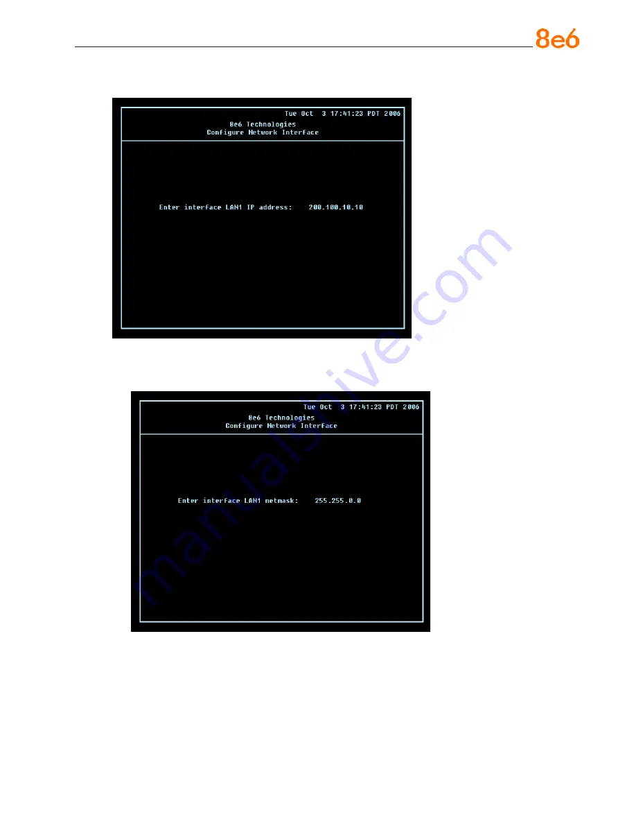
Configure Network Interface screen

A.  At the 

Enter interface LAN1 (eth0) IP address

 field, enter the IP address for the 

LAN 1 (Ethernet 0) interface, and then press 

Enter

 to go to the next screen.


B.  At the 

Enter interface LAN1 (eth0) netmask

 field, enter the subnet mask for the 

LAN 1 (Ethernet 0) interface using the dotted decimals notation format. Press 

Enter


to display the confirmation prompt.

Summary of Contents for 5K02-62

Page 1: ...8e6R QUICK START GUIDE 8e6R Model TAR 1 0 TAR S 5K02 62 TAR H 5K02 66 TAR MSA 5K02 67 Release 1 1 00 Version No 06 18 07 Threat Analysis Reporter ...

Page 2: ...ologies makes no war ranties with respect to this documentation and disclaims any implied warranties of merchantability and fitness for a particular purpose 8e6 Technologies shall not be liable for any error or for incidental or consequential damages in connection with the furnishing performance or use of this manual or the examples herein The information in this documentation is subject to change...

Page 3: ...ll the H Server Bezel 8 Rack Mount the H Server 11 Install the Server 14 Step 1 Initial Setup Procedures 14 Step 2 Physically Connect the Unit to the Network 29 Step 3 Wizard Setup Procedures 30 Conclusion 42 Specifications 43 Physical Specifications 43 Internal Product Specifications 43 Hardware Component Specifications 44 S and MSA Front Panel LED Indicators Buttons 45 Appendix Optional Ethernet...

Page 4: ...iv 8e6 Threat Analysis Reporter Quick Start Guide ...

Page 5: ... usage and provides network administrators tools to monitor such threats so management can enforce corporate Internet usage policies Working in conjunction with 8e6 s R3000 Enterprise Filter the Threat Analysis Reporter translates end user Internet activity from the R3000 s logs into dynamic graphical snap shots of network Internet traffic Using remediation tools in the console administrators and ...

Page 6: ...the quick start steps have been completed Specifications This section features hardware specifications and descriptions of front panel LED indicators Appendix Optional Ethernet Tap Installation This appendix explains how to install the optional Ethernet Tap device on your network for bandwidth monitoring if you have a TAR S or TAR H server Conventions Used in this Document The following icons are ...

Page 7: ...2 6111 Domestic US 1 888 786 7999 International 1 714 282 6111 8e6 Taiwan Taipei Local 2501 5285 Domestic Taiwan 02 2501 5285 International 886 2 2501 5285 Procedures When calling 8e6 Technologies regarding a problem please provide the representative the following information Your contact information Serial number or original order number Description of the problem Network environment in which the...

Page 8: ...r Rack Mount Brackets 2 1 End User License Agreement EULA 1 envelope containing a CD ROM with a PDF of the Threat Analysis Reporter User Guide The latest version of the user guide can be obtained from our Web site at http www 8e6 com docs tar_ug pdf NOTE TAR S and H units come with a NetOptics 10 100BaseT Ethernet Tap kit to be installed at your option TAR H units also come with a separate bezel t...

Page 9: ...hear a click sound as a locking tab emerges from inside the rail assembly and locks the inner rail Then depress the locking tab to pull the inner rail completely out Do this for both the left and right side rack rail Install the Chassis Rails Position the fixed chassis rail sections you just removed along the side of the server chassis making sure the five screw holes line up Note that these two r...

Page 10: ...s provided Attach the other assembly to the other side of the rack making sure that both are at the exact same height and with the rail guides facing inward Install the Server into the Rack You should now have rails attached to both the chassis and the rack unit The next step is to install the server chassis into the rack Do this by lining up the rear of the chassis rails with the front of the rac...

Page 11: ...ng the 8e6 server unit into a Telco type rack follow the directions given on the previous pages for rack installation The only difference in the installation pro cedure will be the positioning of the rack brackets to the rack They should be spaced apart just enough to accommodate the width of the Telco rack ...

Page 12: ...e front end of the chassis This portion of the installation process requires you to unpack the unit and be zel NOTE The bezel has been packaged separately from the unit to prevent dam age during shipping Front of bezel Outside of left inner rail Inside front end of left inner rail Inner left rail attached to chassis Pin on right side of bezel ...

Page 13: ...r rail slightly backwards to release it from the clips at the side of the chassis and then lay it down beside the chas sis with the inside of the rail facing up D On the inner rail that is still attached to the chassis insert the bezel pin into the bottom hole of the ear Be sure the pin is pushed all the way in so that it is flush against the ear E Take up the free end of the bezel and also the lo...

Page 14: ...ert the bezel pin into the bottom hole of the ear G Slide the inner rail forward beneath the clips to lock it in place H Screw the inner rail back on the chassis I After it is installed the bezel should drop down when it is gently tugged forward and down ward The bezel should remain upright when raised up and closed ...

Page 15: ...nce from the front rail to the rear rail of the rack Attach a short bracket to the front side of the right outer rail and a long bracket to the rear side of the right outer rail Adjust both the short and long brackets to the proper distance so that the rail can fit snugly into the rack Secure the short bracket to the front side of the outer rail with two M4 screws and the long bracket to the rear s...

Page 16: ... Do this by lining up the rear of the chassis rails with the front of the rack rails Slide the chassis rails into the rack rails keeping the pressure even on both sides you may have to depress the locking tabs when inserting When the server has been pushed completely into the rack you should hear the locking tabs click Finish by inserting and tightening the thumbscrews that hold the front of the s...

Page 17: ...ling the 8e6 server unit into a Telco type rack follow the directions given on the previous page for rack installation The only difference in the installation proce dure will be the positioning of the rack brackets to the rack They should be spaced apart just enough to accommodate the width of the Telco rack ...

Page 18: ... procedures Threat Analysis Reporter unit with AC power cord either one of two options PC monitor with AC power cord and keyboard or PC laptop computer with HyperTerminal and serial port cable and USB DB9 se rial adapter if there is no serial port on your laptop NOTE Before installing the Threat Analysis Reporter server the R3000 server to be used with this server must already be installed and run...

Page 19: ...s Once the Threat Analysis Reporter is powered up proceed to the Step by Step Initial Setup Procedures Serial Console Setup A Using the serial port cable and USB DB9 serial adapter if necessary connect the laptop to the rear of the chassis see images below Rear of the S or MSA chassis Rear of the H chassis B Power on the laptop C Power on the Threat Analysis Reporter by dropping down the face plat...

Page 20: ...ing a serial console follow these procedures to create a HyperTerminal session A Launch HyperTerminal by going to Start Programs Accessories Communica tions HyperTerminal B In the Connection Description dialog box enter any session Name and then click OK to open the Connect To dialog box ...

Page 21: ...ed to the serial port on the laptop probably COM1 and then click OK to open the Properties dialog box dis playing the Port Settings tab D Specify the following session settings Bits per second 9600 Data bits 8 Parity None Stop bits 1 Flow control Hardware E Click OK to connect to the HyperTerminal session ...

Page 22: ...to open the Properties dialog box displaying the Connect To and Settings tabs G Click the Settings tab and at the Emulation menu select VT100 H Click OK to close the dialog box and to go to the login screen NOTE If using a HyperTerminal session the login screen will display with black text on a white background ...

Page 23: ... for the Web interface if using a NAT device Login screen password prompts The login screen displays after powering on the Threat Analysis Reporter unit using a monitor and keyboard or after creating a HyperTerminal session NOTE If the screensaver currently displays on your screen press the Enter key to display the login screen A At the login prompt type in menu B Press the Enter key to display th...

Page 24: ...he administrator password prompt re enter your password s3tup r3k G Press Enter to display the Administration menu where you can begin the step by step initial setup process using the configuration screens H At the Press the number of your selection prompt press 2 to select the Initial Setup step by step process This process takes you to the Configure Network Inter face screen ...

Page 25: ...th0 IP address field enter the IP address for the LAN 1 Ethernet 0 interface and then press Enter to go to the next screen B At the Enter interface LAN1 eth0 netmask field enter the subnet mask for the LAN 1 Ethernet 0 interface using the dotted decimals notation format Press Enter to display the confirmation prompt ...

Page 26: ... the IP address for the LAN 2 Ethernet 1 interface and then press Enter to go to the next screen E At the Enter interface LAN2 eth1 netmask field using the dotted decimals nota tion format enter the subnet mask for the LAN 2 Ethernet 1 interface Press Enter to display the confirmation prompt F Press Y for Yes to confirm and save your entries for the eth1 interface and to go to the Configure defaul...

Page 27: ...e Enter default gateway IP field enter the IP address for the default gateway Press Enter to display the confirmation prompt B Press Y for Yes to confirm and save your entry for the gateway IP address and to go to the Configure Domain Name Servers screen Configure Domain Name Servers screen ...

Page 28: ...o to the next screen B At the Enter optional second DNS server IP field if you have a secondary Do main Name Server you wish to use enter the IP address for that server Press Enter to display the confirmation prompt C Press Y for Yes to confirm and save your entries for the domain name servers and to go to the Configure Host Name screen Configure Host Name screen ...

Page 29: ...prompt B Press Y for Yes to confirm and save your entry for the host name and to go to the Time zone regional configuration screen Time zone regional configuration screen A Use the up and down arrows in your keyboard to select your region After selecting your locality press Y for Yes to confirm and save your regional selection and to go to the next screen ...

Page 30: ...and save your regional selection and to go to the Configure Wizard user screen Configure Wizard user screen A At the Enter wizard user name field enter the username that will be used to access the setup wizard in the Threat Analysis Reporter interface Press Enter to display the confirmation prompt B Press Y for Yes to confirm and save your entry and to go to the next screen ...

Page 31: ... NOTE When saving your entries there may be a 4 10 second delay before the Administration menu displays Administration menu After making all entries using the step by step initial setup process you will return to the Administration menu Press X to return to the System Configuration screen Or to verify the status of the Threat Analysis Reporter and review the entries you made using the wizard press...

Page 32: ...ent status Active or Inactive Default gateway IP address specified in screen 5 Configure default gateway Configure host name specified in screen 7 Configure Host Name DNS server IP address es specified in screen 6 Configure Domain Name Servers Current status of the Threat Analysis Reporter Current Version of the Threat Analysis Reporter software NOTE Modifications can be made at any time by return...

Page 33: ... Tap unit will be installed for bandwidth monitoring A Plug one end of a standard CAT 5E cable into the Threat Analysis Reporter s LAN 1 port the port on the left Rear of the S and MSA chassis Rear of the H chassis B Plug the other end of the CAT 5E cable into an open port on the network switch Bandwidth Management If you choose to install the Ethernet Tap for bandwidth monitoring you will need to...

Page 34: ...method to be used IP group or LDAP 8e6 Enterprise Reporter server IP address and server name if an ER unit is con nected to the R3000 Access the Threat Analysis Reporter Administrator Console A Launch Internet Explorer B In the address field type in http x x x x 8080 8e6tar wizard html in which x x x x represents the eth0 IP address entered in the Connect Network Interface screen of the Step by St...

Page 35: ...on Log in to the Threat Analysis Reporter Adminis trator Console Log in to the Threat Analysis Reporter Administrator Console A In the Username field of the Login dialog box type in the username specified in the Configure Wizard user screen of the Step by Step Initial Setup Procedures In our example this entry would be taruser B In the Password field type in the password specified in the Configure...

Page 36: ...g into the Threat Analysis Reporter Administrator console The global administrator has the highest level of permissions in the Threat Analysis Reporter interface B Enter the password to be used with that username and enter the same password again in the confirm password field C Enter the email address of the global administrator who will be notified via email when gauges reach their specified uppe...

Page 37: ...ange Information dialog box E Enter the IP address range for the bandwidth the Threat Analysis Reporter will moni tor F Enter the Netmask for the IP range to be monitored using the dotted decimals nota tion format G Click OK to close the dialog box and to display your entries in the list box ...

Page 38: ... display the Remove tab to the left of the Add tab To modify the entries made for the IP address range click the Add tab to re open the IP Range Information dialog box and edit information as necessary Click OK to close the dialog box and to display the modified information in the list box To remove the entry for the IP address range from the list box click the Re move tab Click the Add tab to ope...

Page 39: ... the R3000 server to be used with the Threat Analysis Re porter In our example this is 200 100 160 74 which is the Ethernet 1 IP address of the R3000 server C Enter the Server Name of the R3000 to be used with the Threat Analysis Reporter which is any name you wish to associate with that R3000 In our example this is R3000LOGO D Respond to the question Is this your Master R3000 by clicking the Yes ...

Page 40: ...the list box NOTE Additional R3000 servers can be included by clicking the Add tab again and making the entries described in steps A through E above To modify an R3000 entry double click the R3000 entry in the list box to highlight it and to display the Set as Master tab and the Remove tab to the left of the Add tab ...

Page 41: ...aster tab to display Master in the Master column for that entry in the list box To remove the entry for the R3000 server from the list box click the Remove tab F Specify the User Authentication method to be used for monitoring activity on the Threat Analysis Reporter server LDAP or IP group ER Respond to the question Do you have an Enterprise Reporter by clicking the radio button corresponding to ...

Page 42: ...le this is 200 10 101 76 B Enter the Server Name of the ER server to be used with the Threat Analysis Reporter In our example this is er4logo C Click NEXT at the bottom right of the screen to go to Step 3 NOTE Upon clicking NEXT the wizard will verify whether the settings made in Step 1 and Step 2 are correct If there is an error in any entry made an orange asterisk flashes beside the field in whi...

Page 43: ...gging into the Administrator console NOTE Return to Step 1 or Step 2 by clicking the BACK button in the lower left corner of this wizard screen Specify Gauge Groups to be Monitored By default all Gauges displayed in this wizard screen Adult Content Security Shop ping Bandwidth Illegal are selected for monitoring To deselect a gauge from the Gauge Groups list remove the checkmark by clicking the ch...

Page 44: ... amount 0 or zero that will represent the lower end of the gauge can be adjusted to accommodate the type of activity to be monitored on your network Higher Limit The default amount 200 that will represent the higher end of the gauge can be adjusted to accommodate the type of activity to be monitored on your network Gauge Components To remove a gauge component go to the Selected column and click th...

Page 45: ...ft corner of this wizard screen After reviewing the information in this screen the following actions can now be per formed To print this information click the Print button To save all settings entered during the wizard process click Save After your infor mation is saved the login dialog box of the Threat Analysis Reporter interface dis plays and you can begin using the application NOTE To shut dow...

Page 46: ... Reporter quick start proce dures Now that the Threat Analysis Reporter is running on your network the next step is to set up user groups or administrator groups You will set up and configure gauges thereafter Obtain the latest Threat Analysis Reporter User Guide from our Web site at http www 8e6 com docs tar_ug pdf ...

Page 47: ...1 inch 25mm 1 inch 25mm 1 inch 25mm Rear clearance 3 6 inches 92mm 3 6 inches 92mm 3 6 inches 92mm Weight 19 5 lbs 8 85 kg 43 0 lbs 19 5 kg 11 lbs 5 oz 5 13 kg Internal Product Specifications Specification S Value H Value MSA Value CPU 2 0GHz P4 CPU 2x3 6GHz Xeon CPU 2 0GHz Celeron CPU Memory 3GB PC4200 DDR2 533 Dual Channel ECC RAM 3GB PC2700 DDR 333 ECC SDRAM 3GB PC2700 DDR 333 Dual Channel RAM ...

Page 48: ...00 240V 50 60Hz 5 3 Amp 100 240V 60 50Hz 10 5 Amp per power supply module two mod ules included in the chassis 100 240V 60 50Hz 5 3 Amp Rated input frequency 50 60 Hz 50 60 Hz 50 60 Hz Rated input current 5A MAX 10A 115V to 5A 230V 5A MAX Rated output power 260W 560W 260W Maximum rated BTU 1370 BTUs Hr N A see specs below N A see specs below Nominal DC output 3 3V 15 0A 21 0A 15 0A Nominal DC outp...

Page 49: ...of a feature on the unit while buttons let you per form a function on the unit LED Indicators and Buttons LED Indicator Key Button Key A Power F Reset B HDD Activity G Power C LAN 1 D LAN 2 E Overheat LED Indicator Color Condition Description Power Green On System On Off System Off HDD Amber Blinking HDD Activity Off No HDD Activity LAN 1 LAN 2 Green On Link Connected Blinking LAN Activity Off Dis...

Page 50: ...all accessories are included Save all packing materials in the event that the unit needs to be returned to 8e6 Technologies The NetOptics box should contain the following items 1 NetOptics 10 100BaseT Tap 2 Power Supply units 2 AC Power cords 2 Crossover cables 2 Straight through cables 1 Installation Guide Other Required Installation Items In addition to the contents of the NetOptics box you will...

Page 51: ... procedures outlined in this step require the use of a CAT 5E cable A Provide power to the Ethernet Tap by connecting both power cords from the unit to the power source AC power in rear panel of NetOptics 10 100BaseT Tap B If a designated master R3000 to be used with the Threat Analysis Reporter is al ready installed on the network disconnect the cable that connects this R3000 to the switch If the...

Page 52: ... the other end of the crossover cable to the Ethernet Tap s Network A port Ports in front panel of NetOptics 10 100BaseT Tap E Using a straight through cable connect one end to the Ethernet Tap s Network B port F Connect the other end of the straight through cable to the R3000 s listening interface G Using the second straight through cable connect one end to the Ethernet Tap s Monitor A port H Con...

Page 53: ...8e6 Threat Analysis Reporter Quick Start Guide 49 8e6 Threat Analysis Reporter Quick Start Guide 49 Tap Installation ...

Page 54: ...e Orange CA 92865 4232 Tel 714 282 6111 or 888 786 7999 Fax 714 282 6116 Sales Technical Support 714 282 6117 General Office Satellite Office 8e6 Taiwan RM B2 13F No 49 Sec 3 Minsheng E Rd Taipei 104 Taiwan R O C Tel 886 2 2501 5285 Fax 886 2 2501 5316 ...

Reviews: