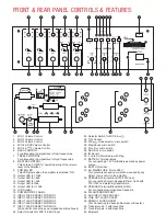
FRONT & REAR PANEL CONTROLS & FEATURES:
1. MIC-1 Volume Control
2. MIC-2 Volume Control
3. MIC-3 Volume Control
4. MIC-4 & AUX Volume Control
5. MIC-5 & Volume Control
6. BASS CONTROL
For attenuating the signal level of low frequencies.
7. TREBLE CONTROL
For attenuating the signal level of high frequencies.
8. MASTER CONTROL
This acts as a GATE for overall opening of the volume
level of the Amplier.
9. POWER LED
This LED glows when the amplier is switched 'ON'.
10. Output LED for -13db
11. Output LED for -8db
12. Output LED for -3db
13. Output LED for 0db
14. Output LED for +13db
15. LCD Display
16. POWER ON/OFF Switch
17. INPUT JACK SOCKET FOR MIC-1
18. INPUT JACK SOCKET FOR MIC-2
19. INPUT JACK SOCKET FOR MIC-3
20. INPUT JACK SOCKET FOR MIC-4
21. INPUT JACK SOCKET FOR MIC-5
(All Jacks for connecting Low impedance microphones)
22. Selector Switch for MIC-4 & AUX input
23. Selector Switch for MIC-5 &
24. Socket
25. FM/ mode selector micro switch
26. Play/Pause micro switch
27. Prev/CH- micro switch
28. Next/CH+ micro switch
29. IR Sensor
30. 3 Core AC Main Cable with Plug
31. BATTERY Terminal Block
For connecting a 12V Car Battery as standby power
source.
32. EARTH Terminal
33. AC MAINS FUSE 3 Amp 250V
This prevents excessive current ow caused by any
defect / short circuit in the amplier.
34. SPEAKER Terminal Block(70V/100VLine)
For connecting Column Speakers/Driver Units with
70V/100V line matching transformers.
35. SPEAKER Terminal Block(4Ω,8Ω,16Ω)
For connecting low impedance Speakers.
36. FM ANTENNA SOCKET
37. AUX INPUT JACK SOCKET
38. LINE OUT JACK SOCKET
39. PREOUT JACK SOCKET
(For Connecting to Cassette Recorder or Booster.)
40. Transistor pair -1 with Heat Sink
41. Transistor pair -2 with Heat Sink
42. Bluetooth
40
1
2
3
4
5
24
10 11 12
13 14
15
17
18
19
20
21
22
23
6
25
26
7
27
8
28
29
9
16
36
37
38
41
39
34
35
32
30
33
31
2
5C AMP 120W DLX BT
5C AMP 120W DLX BT


