background image

New Advanced Operational Features

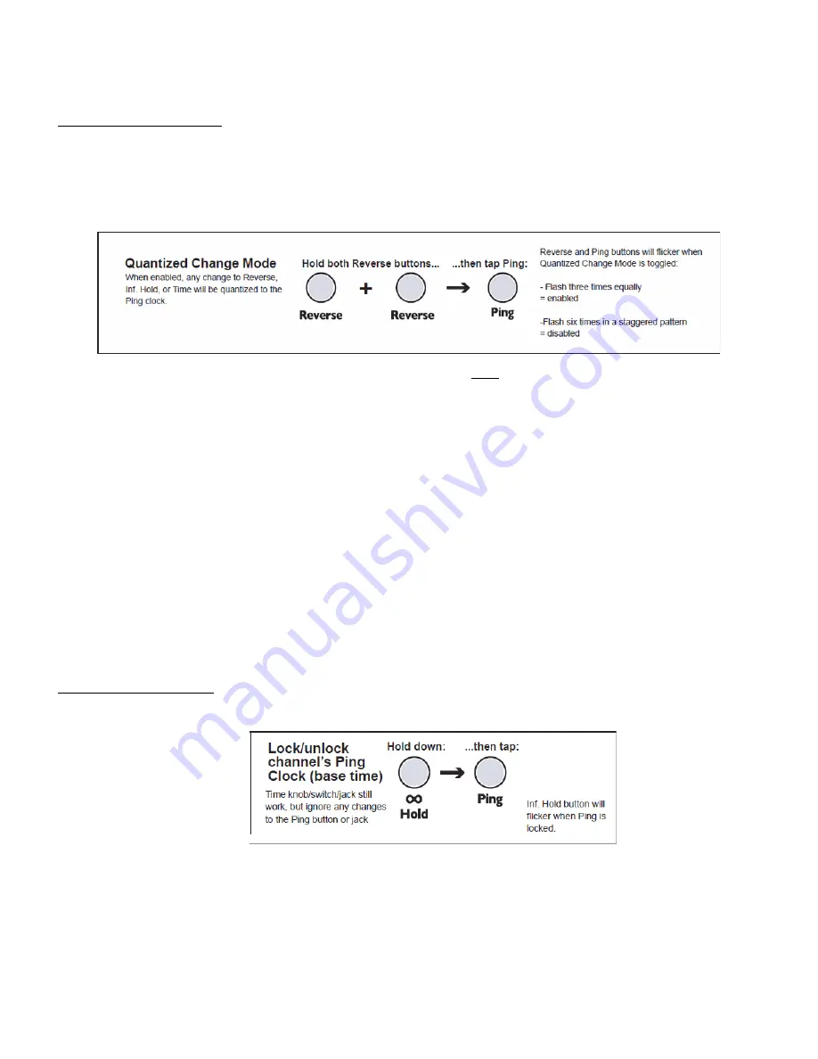
Quantized Change Mode: Modulation ‘on the beat’

‘Normally’, the DLD controls of 

Time

Reverse A/B

, and 

Infinite Hold A/B 

operate as you would expect in most any 

device. Changes to the control take effect immediately, no matter when they occur. In the 

Quantized Change Mode


(or ‘

QCM

’), any change to these parameters (on both channels) will be delayed until the next pulse of the 

Ping Clock

This has great implications for working in synch with rhythm devices and complex patches.

The factory default setting for 

QCM

 is ‘off’. To enter 

QCM

, hold down both of the 

Reverse

 buttons and tap the 

Ping


button once. The two 

Reverse

 lamps will flash 3 times evenly to show entry into 

QCM

. Exit 

QCM

 with the same 

procedure, in which case the same lamps flash 6 times in a staggered pattern.

QCM

 is best explored with a rhythmic patch, sequencer, or drum unit locked with the DLD clock (DLD can be master 

of slave. Asynchronous modulations and triggers can be used freely, since they will be ‘force synch’d’ to the 

Ping


clock. In this sense, 

QCM

 might be thought of as a kind ‘Sample and Hold’ that locks modulation sources with the 

fundamental time. Go ahead, experiment! It can be addicting.

One note in passing is that ‘free modulating’ the 

Reverse

 in this mode can lead to quite a lot of ‘Memory Scraps’ that 

come back at surprising times, especially when the Reverse switching continues after input source is killed. This can 
be a real plus (as well as a real surprise) as these bits and pieces will remain locked to the clock. If it gets out of hand, 
you can use the 

Memory Clear

 function, or discontinue triggers to Reverse so that the ‘scraps’ eventually clear 

themselves out.

You can save 

QCM

 as your default power-up state by switching it ‘on’ and entering 

System Mode

 and saving as 

described later and in the full DLD manual.

Lock Channel Ping Time: Resonant Delay Melody and Echo at the same time

In firmware version 5, either channel’s response to the 

Ping

 clock can be locked at its current value. The procedure is 

to hold down the 

Inf Hold

 button of the channel you want to ‘lock’ and tap the 

Ping

 button once. Use the same 

procedure to restore normal operation. The setting is not saved, and the unit will always power up responding 
normally to 

Ping

 clock on both channels

An example application for 

Locking Channel Ping

 is when you want to use one channel for short-delay resonance 

effects whose pitch is modulated by a fast clock on the 

Ping 

input. Locking the opposite channels’ 

Ping

 time allows for 

use of that channel for standard delay effects, on the resonant channel’s output or any other source.

Summary of Contents for DLD

Page 1: ...rate notifications and close applications such as Facebook that use audio notification Any disruption in the audio will ruin the process Updating 4 To enter the Audio Bootloader mode depress both Reverse buttons A and B and the Ping button while powering on the DLD When you see the Channel A Hold button turn on or blink the DLD is ready to receive firmware Release all the buttons 5 Begin playing t...

Page 2: ...ash 6 Now flip Time A up Time B down 7 Hold down all five buttons Rev A Inf A Rev B Inf B Ping for 10 seconds 8 Release the buttons when you see the lights make a chase sequence 9 Power off and power back on The DLD has now been reset to its factory default settings New Features and Enhancements New Feature High Resolution Audio 24 bit Audio Operation The DLD can now operate with superb full 24 bi...

Page 3: ...n passing is that free modulating the Reverse in this mode can lead to quite a lot of Memory Scraps that come back at surprising times especially when the Reverse switching continues after input source is killed This can be a real plus as well as a real surprise as these bits and pieces will remain locked to the clock If it gets out of hand you can use the Memory Clear function or discontinue trig...

Page 4: ...nced for greater ease of use In entering and using the System Settings mode the position of the channel toggle switches upper left and upper right determines what happens With that in mind the function available in System Settings are here organized into groups according to the position of these two switches Many of the System Settings functions are inherited from Version 4 These are included here...

Page 5: ... recommend the factory default setting of 8 ms Volt Octave Tracking Compensation A and B from Version 4 The tracking of the Time CV jack when the channel is in Unquantized Time Mode See Owners Manual for details on this mode can be adjusted to compensate for keyboards or sequencers that are not accurate or to provide alternate tunings See the earlier section for a discussion on Unquantized Time Mo...

Page 6: ...These methods are suited for syncing to clocks that have a small amount of jitter and no drift where tiny differences in clock speed don t matter but you want the DLD to respond quickly to large changes in tempo Locking to a drum loop that changes tempo from 120BPM to 90BPM for example is an example where you may want to use these settings ECD Disabled one to one This method simply makes the DLD s...

Page 7: ...cation of this with regard to reverse is use a variable PW pulse wave as the gating source It does time stretching easily with some really interesting time stretching that can make sounds slow down or even go backwards Note that the limits of this effect heavily depend on the Cross fade time described below Some recommended settings for initial experimentation Cross fade time set to 8ms factory de...

Page 8: ...things too quiet too quickly so the use of Linear Taper compensates for that In Version 5 Linear Taper is not the default but can be changed by the user With Linear Taper iIf you have a very hot input signal you should keep Delay Feed below 50 so that it doesn t saturate Runaway DC Blocking NEW FEATURE Hardware on the DLD inputs eliminates most DC offset but it s still possible for a small amount ...

Page 9: ...oint Below this point the signal is unaffected This saturation distortion sounds is often more pleasing to hear versus harsh clipping In most cases it is not necessary to disable soft clipping System Settings The Up Down Group Version 4 legacy Loop and Main Clock Output Duty Cycle The clock output jacks can output gates or triggers 22ms pulse width In this mode the loop lights and Ping light will ...

Page 10: ...will allow you to audition changes without saving It s a good idea to form the habit of putting your toggle switches back to their desires positions for operation as soon as you exit System Settings mode Otherwise you can forget and find yourself with a much longer delay time than you expected Want to know more The completely updated version 5 User Manual for the DLD contains more discussion and e...

Reviews: