background image


Quick Installation Guide 

OWL630  Enterprise  Access  Point 

ENGLISH 

Copyright ©  4IPNET, INC. All rights reserved.   


Step 3. 

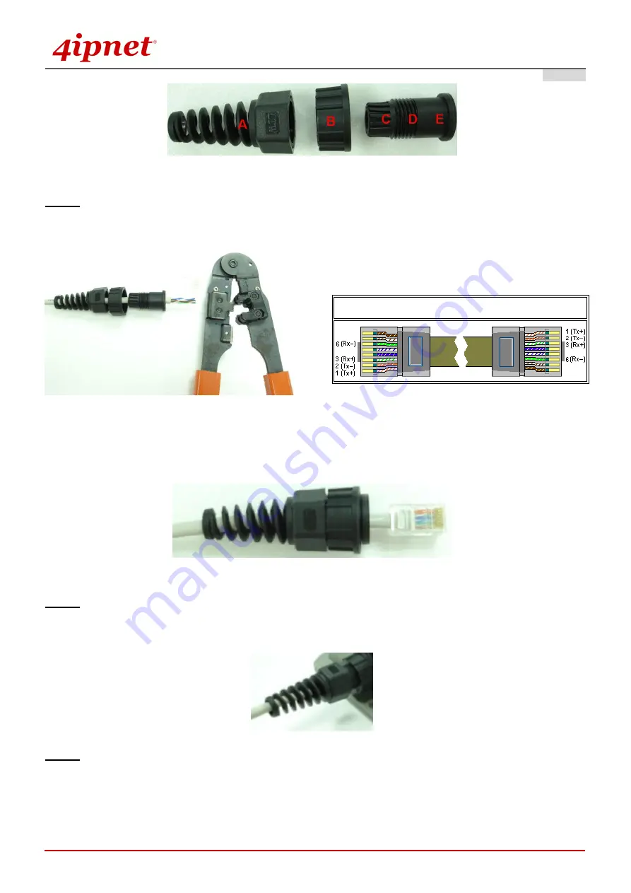
Insert  the  cable  through  the  main  parts  and  install  a  RJ-45  connector  using  straight-through  method 

(both ends are in the same wiring order: 1 (Tx+), 2 (Tx-), 3 (Rx+), 6 (Rx-)). 


Example after the RJ-45 connector is installed, 


Step 4. 

Plug the RJ-45 Connector into the system and make sure the locking ring is locked in well. 


Step 5. 

Coil waterproof tape to secure the parts of the Waterproof Connector Pack. 


Straight-Through Cable Wiring 


Summary of Contents for OWL630

Page 1: ...OWL630 V1 00 Outdoor Access Point ...

Page 2: ... not copy reproduce distribute publish display perform or modify any part of this publication in any form or by any means without prior written permission from 4IPNET INC You may not alter or remove any copyright or other notice from copies of the content All other brand and product names are claimed or registered marks of their respective companies or organizations All rights reserved To download...

Page 3: ...n If this equipment does cause harmful interference to radio or television reception which can be determined by turning the equipment off and on the user is encouraged to try to correct the interference by one or more of the following measures Reorient or relocate the receiving antenna Increase the separation between the equipment and receiver Connect the equipment into an outlet on a circuit diff...

Page 4: ...y EN 60950 1 A11 Caution This declaration is only valid for configurations combinations of software firmware and hardware provided and supported by 4ipnet Inc The use of software or firmware not provided and supported by 4ipnet Inc may result in the equipment no longer being compliant with the regulatory requirements European standards dictate maximum radiated transmit power of 100mW EIRP and freq...

Page 5: ...pliant It is high wind load resilient and is designed to operate in a wide range of temperature Flexible deployment with a variety of antennas allows OWL630 to easily serve clients located in different directions as well as for coverage extension This Quick Installation Guide including FAQ Instruction Guide provides instructions for getting started with the OWL Access Point 1 4ipnet OWL630 x 1 2 Q...

Page 6: ...2 System Overview OWL630 Top Back N type Connector x 6 For connecting to an antenna RF Card A x 3 RF Card B x 3 Connector marked 1 is for the primary antenna when the AP is not in 802 11n or 802 11ac mode Utilize all connectors for optimized MIMO performance Ground Connector For connecting the ground wire ...

Page 7: ...he OWL630 may condense The valve allows ventilation to prevent moisture buildup within the OWL630 3 Uplink PoE Connector For connecting to the Power Sourcing Equipment PSE 4 Ethernet LAN Attach Ethernet cables here for connecting to the wired local network 5 Console The system can be configured via a serial console port The administrator can use a terminal emulation program such as Microsoft s Hyp...

Page 8: ...ernet Port of OWL630 to the POWER DATA OUT Port of the PSE Step 3 Connect one end of an Ethernet cable to the Data Port of PSE and the other end to the computer Step 4 Power on the PSE in order to supply power to the OWL630 Installing the Waterproof Connection Pack A connector pack as shown in the figure below is included with the system Parts Included 5 Parts Part A Part E Step 1 Take the white s...

Page 9: ...ll a RJ 45 connector using straight through method both ends are in the same wiring order 1 Tx 2 Tx 3 Rx 6 Rx Example after the RJ 45 connector is installed Step 4 Plug the RJ 45 Connector into the system and make sure the locking ring is locked in well Step 5 Coil waterproof tape to secure the parts of the Waterproof Connector Pack Straight Through Cable Wiring ...

Page 10: ...g the Waterproof Connection Pack Optional The M12 Waterproof Connector Pack is used for DC power supply and it consists of 5 parts Step 1 Pass power cable through the Sealing Nut Gaskets and Clamp Ring items 2 5 Step 2 Solder power pins with reference to the pin definition below Pin Number Pin Definition 1 V 3 V 4 NC ...

Page 11: ...ght 4IPNET INC All rights reserved 7 Step 3 Seal all connectors and fasten sealing nuts Now the Hardware Installation is complete For installation instruction on mounting please refer to the Outdoor Installation Guide 4ipnet_TEC_Outdoor_Installation_Guide_R2_20140220 pdf ...

Page 12: ...68 1 1 Subnet Mask 255 255 255 0 Steps 1 To access the web management interface connect the administrator PC to the LAN port of OWL630 via an Ethernet cable Then set a static IP address on the same subnet mask as OWL630 in TCP IP of your PC such as the following example IP Address 192 168 1 100 Subnet Mask 255 255 255 0 2 Launch the web browser on your PC by entering the IP address of OWL630 https...

Page 13: ... successful login into OWL630 s Web user interface Web UI a System Overview page of web management interface will appear as depicted below The Web Management Interface System Overview Page 5 To logout simply click on the Logout button at the upper right hand corner of the interface to return to the Administrator Login Page Click OK to logout ...

Page 14: ...n Settings Step 1 Change Administrator s Password Change Password Page Click on the Utilities main menu button and then select the Change Password tab Enter the old password and then a new password with a length of up to 32 characters and retype it in the Re enter New Password field Click SAVE to save the changes ...

Page 15: ...ect your preferred Band and Channel for you wireless connection For example select 802 11g 802 11n for the band and 1 for the channel Note Admin should be aware of Dynamic Frequency Selection DFS mandated on some channels of the 5GHz band When OWL630 detects interference this mechanism will limit the ability to broadcast the SSID on one of the channels listed below 1 Country Code 841 US DFS Channe...

Page 16: ...hown OWL630 supports up to 16 virtual APs per RF card VAPs Configure VAP profile settings a Select the VAP Configuration tab to configure the settings of the desired VAP b Enable a specific VAP from the drop down menu of Profile Name and configure related settings below Check VAP status After finishing VAP configuration the status of enabled Virtual APs shall be reflected on the VAP Overview page ...

Page 17: ...Quick Installation Guide OWL630 Enterprise Access Point ENGLISH Copyright 4IPNET INC All rights reserved 13 Virtual AP Overview Page ...

Page 18: ...DS as the Repeater Type Choose the desired WDS profile a Enable the WDS b Enter the MAC Address peer AP and then Click SAVE If you use another OWL630 as the peer AP simply repeat the above mentioned steps to configure another peer AP s Note On each and every configuration page you may Click SAVE to save the changes but you must reboot the system upon the completion of all configuration settings fo...

Page 19: ...ase remember to change the IP Address of your PC Connection Properties back to its original settings in order to ensure that your PC functions properly in its real network environments It is strongly recommended to make a backup copy of the configuration settings For further configuration and backup information please refer to the User s Manual P N 10020141120 ...

Reviews: