background image

49


User Manual ENGLISH 


EAP/OWL-Series Wave 2 Enterprise Access Point


Copyright ©  2017, 4ipnet, Inc. All rights reserved. All other trademarks mentioned are the property of their respective owners. 
 

Reset to Default 
Typically, administrators can reset the system to factory default from the Web Management Interface as 
below description. Additionally, there is another way to from the Console Interface and just refer to 

session 8.2 Remote Connection by SSH Interface”


Keep Network Interface Settings: in some cases, it is helpful to check this option to ensure the 
original Network Interface settings remain even after a system reset-to-default. 

Keep VLAN for Management: in some cases, it is helpful to check this option to ensure the original 
VLAN for Management settings remain even after a system reset-to-default. 

Click 

Reset

 to load the factory default settings. A pop-up message will appear to re-confirm the 

request to reboot the system. Click 

OK

 to proceed, or click 

Cancel

 to cancel the action. 


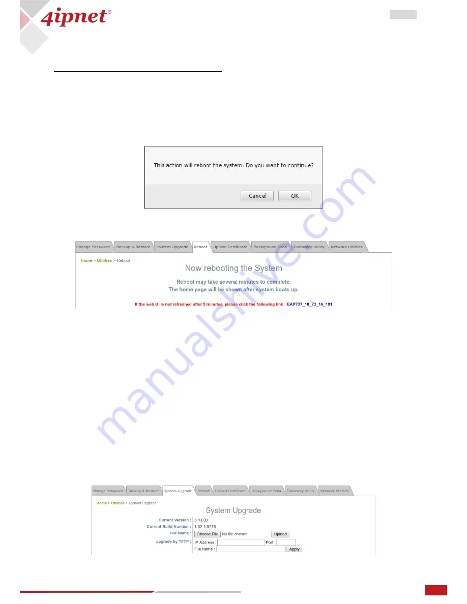
A message as displayed below will appear during the reboot period. The system power must be 
kept on before the completion of the reboot process. The System Overview page will appear upon 
reboot completion. 


Backup System Settings: to save the current system configurations to a backup file on a local disk of the 
management console. A backup file can be restored to the system by clicking 

Choose File

 button to select 

the backup file and then clicking 

Restore

 button to execute the process. 

 
Restore System Settings: to click 

Choose File 

to search for a .db database backup file created by the 

controller and click 

Restore 

to restore to the same settings at the time when the backup file was saved.  


6.3


System Upgrade 

There are two methods of firmware upgrade: via the WMI or via a TFTP server. The administrator can 
obtain the latest firmware from the 4ipnet Support Team. To upgrade the firmware, click “Choose File” to 
select the new firmware file you downloaded onto your PC and then click “Upload” to execute the 
process. To upgrade by TFTP, enter the designated IP address, Port, and File Name, then click “Apply”. 
Please restart the system after upgrading the firmware. 


Summary of Contents for EAP737

Page 1: ...roprietary information which is the property of 4IPNET INC and is strictly confidential No part may be reproduced except as authorized by written permission of the contributing companies User Manual EAP OWL Series Wave 2 Enterprise Access Point Verion 3 43 00 ...

Page 2: ...ace 14 3 3 DHCP Server 16 3 4 Management 17 3 5 CAPWAP 18 3 5 1 To Managed by WLAN Controller with Complete Tunnel 19 3 5 2 To Managed by WLAN Controller with Complete Tunnel 21 3 6 IPv6 23 3 7 iBeacon 23 3 8 RTLS 24 3 9 DPI DNS 24 4 Wireless 25 4 1 VAP Overview 25 4 2 General 28 4 3 VAP Config 31 4 4 Security 33 4 5 Repeater 37 4 6 Advanced 38 4 7 Access Control 40 4 8 Hotspot 2 0 42 5 Firewall 4...

Page 3: ...ioned are the property of their respective owners 7 Status 54 7 1 Overview 54 7 2 Interfaces 55 7 3 Associated Clients 55 7 4 DHCP Lease 56 7 5 Link Status 56 7 6 Event Log 57 7 7 Wireless Log 57 7 8 Monitor 58 8 Console Interface 59 8 1 Direct Connection by Console Cables 59 8 2 Remote Connection by SSH Interface 60 9 Hardware Overview 61 ...

Page 4: ... and for the AP to allow Wi Fi devices to connect to the wired network 1 1 Log in to the AP The AP has a web based interface for configuration and management To access the Web Management Interface WMI for the first time follow the steps below 1 Ensure that your administrative PC is manually set to a static IP Address in the same subnet as the AP s 192 168 1 0 255 255 255 0 Connect the PC directly ...

Page 5: ...emarks mentioned are the property of their respective owners 3 System Overview page of the WMI will appear after login 4 Change the administrator s password for security reasons Click on the Utilities icon on the main menu and select the Change Password tab Enter the New Password and retype it in the Re enter New Password field ...

Page 6: ...tion Go to System General page Home System General to configure general information for the AP 1 System Information Enter appropriate system related information Name Description and Location by which administrators will be able to identify the AP in the network 2 Time For this initial configuration set the system time for the AP using the method of Enable NTP to sync the system clock with Network ...

Page 7: ...terface to perform configuration of the network settings Mode Static Manually fill in appropriate values for the network interface IP Address Netmask Default Gateway and Primary DNS Server in the example above the AP is still using the default IP address 192 168 1 1 DHCP If the deployment requires that the AP get a dynamic IP Address from the LAN set Mode to DHCP Click SAVE to submit the changes S...

Page 8: ...e profile This will bring up the following VAP Configuration page Note Virtual Access Point VAP VAP feature allows a single physical AP device with a unique single BSSID to present itself as multiple discrete APs as shown in the example diagram below Each VAP can be independently enabled or disabled with its own settings e g SSID Network Mode VLAN ID Security etc such that the AP is able to suppor...

Page 9: ...Translation NAT device with a built in DHCP server on this SSID such that client devices will be assigned a dynamic IP address from the configured DHCP pool on this SSID After NAT conversion the source IP address of client traffic seen by the uplink gateway switch will be the IP address of the AP in this case 192 168 1 1 as shown in the diagram below VLAN ID Per SSID VLAN tagging function when ena...

Page 10: ...tenna Mode 2T2R Channel Width 80 MHz Channel 36 You can make changes to other settings at a later time Congratulations After a system restart the AP should be able to operate with these settings DHCP Profile and DHCP Server are activated only when the VAP is set to NAT mode If the VAP is in NAT mode the CAPWAP Tunnel Interface will only work in two states Disable No Tunnel or Split Tunnel Note SSI...

Page 11: ...Firewall List Change Password Overview Network Interface General Service Backup Restore Interfaces DHCP Server VAP Config Advanced System Upgrade Associated Clients Management Security Reboot DHCP Lease CAPWAP Repeater Upload Certificate Link Status IPv6 Advanced Background Scan Event Log iBeacon Access Control Discovery Utility Wireless Log RTLS Hotspot 2 0 Network Utilities Monitor DPI DNS Note ...

Page 12: ... information on geographical location of the system for the administrator to locate the system easily Time Device Time Display the current system time Time Zone Select an appropriate time zone from the drop down list box Time There are two methods of setting up the time Enable NTP Synchronize the system clock with Network Time Protocol NTP server Simply enter the IP Address or domain name of a loc...

Page 13: ...ed are the property of their respective owners Click APPLY after an alert message Some modifications have been saved and will take effect after APPLY appears on the WMI Unless Internet connection or NTP becomes unavailable it is recommended to use NTP server for time synchronization because the system time needs to be reconfigured upon reboot ...

Page 14: ...erver automatically Ethernet IGMP Snooping When Enabled the switch forwards traffic IGMP packets are transferred via the Access Point s network interface and the IP multicast host Registration information is recorded and sorted into multicast groups The internal switch forwards traffic only to those ports that request multicast traffic Adversely without IGMP snooping multicast traffic is treated l...

Page 15: ...15 User Manual ENGLISH EAP OWL Series Wave 2 Enterprise Access Point Copyright 2017 4ipnet Inc All rights reserved All other trademarks mentioned are the property of their respective owners ...

Page 16: ...t devices will be assigned a dynamic DHCP IP address from the configured DHCP pool on the SSID The NAT and DHCP mode can be executed without tunnel or managed by 4ipnet WLAN controller with split tunnel It is noted that Pool1 Pool16 are all configured as A class DHCP IP addresses as default values and only configurable at AP s Web Management Interface It starts from 10 101 0 254 16 to 10 116 0 254...

Page 17: ...The system allows 5 SNMP Users with Read or Read Write Access Determine the Name and Authentication Password on the SNMP Account List Trap When enabled events on Cold Start Interface UP Down and Association Disassociation can be reported to the assigned server Server IP Address Enter the IP address of the assigned server that will receive the trap report Syslog Level Select the desired level of re...

Page 18: ...o enable this item select Enable and click Manage Certificates to enter the Upload Certificate page Please refer to the section 4 4 5 Upload Certificate DNS SRV Discovery Using DNS SRV to discover acess controller Domain Name Suffix Enter the suffix of the access controller such as example com DHCP Option Discovery Using DHCP option to discover access controller Broadcast Discovery Using Broadcast...

Page 19: ...ic to the internet The WLAN controller is able to implement role based policies over Layer 3 networks with user access control available in the remote sites This feature allows the WLAN controller to fully support centralized AP management and user management The following procedures may be helpful 1 On AP to type the IP address for Static Discovery and wait until the CAPWAP column displays a RUN ...

Page 20: ...l rights reserved All other trademarks mentioned are the property of their respective owners 4 On AP to check the AP WMI showing Data Channel is Active with the VAP tunnel status in Green light on the System Overview page 5 On AP to reconfirm the specific VAP Configuration is under Complete Tunnel ...

Page 21: ... be transmitted with a shorter path and the network load of the controller can also be reduced The following procedures may be helpful 1 On AP to type the IP address for Static Discovery and wait until the CAPWAP column displays a RUN status 2 On WHG to prepare Template of the VAP configuration with CAPWAP Tunnel Interface Split Tunnel 3 On WHG to apply the prepared Template to the CAPWAP establis...

Page 22: ...Series Wave 2 Enterprise Access Point Copyright 2017 4ipnet Inc All rights reserved All other trademarks mentioned are the property of their respective owners 5 On AP to reconfirm the specific VAP Configuration is under Split Tunnel ...

Page 23: ...a wireless connectivity technology The UUID Major and Minor are the identifying parameters used to make up the key component of the iBeacon Advertising Packets that are continually transmitted by the AP UUID Universally Unique Identifier a number to distinguish your own AP in the network from all other iBeacon transmitters in networks outside your control It contains 32 hexadecimal digits split in...

Page 24: ...grate the AP with the dedicated Linkyfi 4ipnet technology partner server of Real Time Location System RTLS which is part of Linkyfi Location Engine an advanced software solution for indoor location and real time navigation in all types of venues 3 9 DPI DNS To perform WiFi marketing analytics customers can enable this feature to integrate the AP with Linkyfi s DNS server which is also part of Link...

Page 25: ...he 4ipnet Access Point supports up to sixteen Virtual Access Points VAPs per RF card Each VAP can have its own settings e g ESSID VLAN ID security settings etc With such VAP capabilities different levels of service can be configured to meet network requirements 4 1 VAP Overview An overall status is collected on this page including ESSID Network Mode State Security Type MAC ACL and Hotspot 2 0 wher...

Page 26: ... property of their respective owners State The hyperlink showing Enable or Disable links to the VAP Configuration page or VAP State Page Security Type The hyperlink showing the security type links to the Security Settings Page VAP Security Type Page MAC ACL The hyperlink showing Allow or Disable links to the Access Control Settings Page VAP MAC ACL Page ...

Page 27: ...e 2 Enterprise Access Point Copyright 2017 4ipnet Inc All rights reserved All other trademarks mentioned are the property of their respective owners Hotspot 2 0 The advanced settings hyperlink links to the Hotspot 2 0 Page VAP Hotspot 2 0 Page ...

Page 28: ...rt guard interval is half of what it used to be please select Enable to use Short Guard Interval or Disable to use normal Guard Interval Antenna Mode Select 1T1R for one spatial stream or 2T2R for two spatial streams Channel Width Double channel bandwidth to 40 MHz or 80 MHz to enhance throughput Channel Select the appropriate channel from the drop down menu to meet the regularity When configured ...

Page 29: ...t of time in seconds where default 300s Band Steering When enabled clients with 5GHz connectivity will be steered towards the 5GHz band to reduce congestion in the 2 4GHz band This is applicable only when the AP is set to 2 4GHz and 5GHz on the 2 RF Cards Aggressive clients with 5GHz connectivity are forced to connect to the 5GHz band Note that this is a general setting for the Access Point and is...

Page 30: ...5 6 7 8 9 10 11 12 13 1M 2M 5 5M 11M 802 11g 1 2 3 4 5 6 7 8 9 10 11 12 13 6M 9M 12M 18M 24M 36M 48M 54M 802 11b 802 11g 1 2 3 4 5 6 7 8 9 10 11 12 13 1M 2M 5 5M 6M 9M 11M 12M 18M 24M 36M 48M 54M 802 11a 802 11n 36 40 44 48 52 56 60 64 100 104 108 112 116 132 136 140 149 153 157 161 165 6M 9M 12M 18M 24M 36M 48M 54M MCS0 23 Level 1 Level 25 model dependent 802 11n 802 11g 1 2 3 4 5 6 7 8 9 10 11 1...

Page 31: ...ate with the specific VAP Network Mode Bridge mode the VAP operates transparently i e no NAT no DHCP such that client devices will be assigned a dynamic IP address from a DHCP server on the LAN side The source IP address of client traffic seen by the uplink gateway switch will remain the original IP address of the client in this case 192 168 1 31 as shown in the diagram below Network Mode NAT mode...

Page 32: ...formation please refer to IEEE Standards 802 1P DHCP Profile for NAT mode Built in DHCP Server profile IP settings of DHCP Server are under Home System DHCP Server CAPWAP Tunnel Interface Three states indicating the connectivity between AP and Controller when AP is managed by Controller Disable No Tunnel the AP is operating with no CAPWAP Tunnel connection to the Controller Split Tunnel the AP pas...

Page 33: ... and data is not encrypted during transmission WEP Wired Equivalent Privacy is a data encryption mechanism based on a 64 bit 128 bit or 152 bit shared key algorithm 802 11 Authentication Select from Open System Shared Key or Auto WEP Key Length Select a key length from 64 bit 128 bit or 152 bit WEP Key Format Select a WEP key format from ASCII or Hex WEP Key Index Select a key index from 1 4 The W...

Page 34: ...on different APs with the same Encryption Key Security Settings WPA Personal Cipher Suite Select an encryption method from WPA2 or WPA2 WPA Protected Management Frames Select Disable Optional or Mandatory Roaming Target AP List when 802 11r is enabled Pre shared Key Type Select a pre shared key type PSK Hex or Passphrase Pre shared Key Enter the key value for the pre shared key the format of the k...

Page 35: ...P List when 802 11r is enabled Group Key Update Period The time interval for the Group Key to be renewed the time unit is in seconds RADIUS Server Settings Primary Secondary o Host Enter the IP address or domain name of the RADIUS server o Authentication Port The port number used by the RADIUS server Specify a port number or use the default 1812 o Secret Key The secret key for the system to commun...

Page 36: ...The system will update accounting information to the RADIUS server every interval period OSEN OSEN stands for The Online Signup OSU Server only authenticated layer 2 Encryption Network which is Hotspot 2 0 Release2 HS2 0 R2 authentication method Before setting HS2 0 R2 we should check the security of each VAP HS2 0 VAP VAP1 WPA Enterprise or OSEN VAP VAP2 OSEN Further configuration detail please c...

Page 37: ...supports up to 8 WDS links to its peer APs per radio Fill in remote peer s MAC address and click SAVE to proceed WDS Enable or Disable the selected WDS Link profile WDS Link Address The MAC address of the AP interface for the selected WDS Link Remote AP MAC Address The MAC address of remote peer Security Type None WEP or WPA Personal CAPWAP Tunnel Interface Check this option to designate WDS traff...

Page 38: ...erated within the periodic beacon at a specified frequency Higher DTIM will allow the wireless client to save more energy but the throughput will be lowered Consecutive Dropped Packets This is the maximum number of transmission retries the AP will attempt when packet transmission is dropped before deciding the client is out of transmission reach When transmission retries fails for the set number o...

Page 39: ...ast broadcast packets If your wireless clients require a larger or smaller bandwidth for sending multicast broadcast packets the administrator can customize the Access Point s multicast broadcast bandwidth here Management Frame Rate This feature controls the bandwidth for Management Frames The higher the rate it the shorter range the transmission covers Receiving RSSI Threshold To ensure connected...

Page 40: ...ue to a desired number For example when the number of stations is set to 20 only 20 stations are allowed to connect to the specified VAP Access Control Type Disable Access Control When Disable is selected there is no restriction for client devices to access the system Access Control Type MAC ACL Allow List When selecting MAC ACL Allow List only the client devices identified by their MAC addresses ...

Page 41: ...s to the system except those listed in the Deny List denied MAC addresses The administrator can allow any denied MAC address to connect to the system temporarily by checking Disable Access Control Type RADIUS ACL Authenticate incoming MAC addresses by an external RADIUS When RADIUS ACL is selected all incoming MAC addresses will be authenticated by an external RADIUS Please note that each VAP s MA...

Page 42: ... consortium is a group of service providers SP with which a user s credentials can be used for authentication Roaming consortiums are identified by an organization identifier OI that is assigned by the IEEE similar to the first half of a MAC address An OI is often 24 bits in length but can also be 36 bits i e OUI 36 IP Address Type IPv4 or IPv6 NAI Realm List An NAI Realm identifies the proper aut...

Page 43: ...on provides information in the following functions Firewall Lists Service and Advanced Firewall Settings 5 1 Firewall List It provides an overview of firewall rules in the system 6 default rules with up to a total of 20 firewall rules are available for configuration From the overview table each rule is designated with the following field No The numbering will decide the priority for the system to ...

Page 44: ... the fields in 802 2 LLC frame header Type when EtherType is IEEE802 3 The field can be used to indicate the type of encapsulated traffic VLAN ID when EtherType is 802 1 Q The VLAN ID is provided to associate with certain VLAN tagging traffic Priority when EtherType is 802 1 Q It denotes the priority level with associated VLAN traffic Encapsulated Type when EtherType is 802 1 Q It can be used to i...

Page 45: ...espective owners To move a specific rule Mv in the Setting column of the firewall list will lead to the following page for reordering confirmation After the SAVE button is clicked and system is rebooted the order of rules will be updated Please make sure all desired rules state of rule are checked and saved in the overview page the rules will be enforced upon system reboot ...

Page 46: ...therType is IPv4 The Access Point provides a list of rules to block or pass traffic of layer 3 or above protocols These services are available to choose from a drop down list of layer2 firewall rule edit page with Ether Type IPv4 The first 28 entries are default services and the administrator can add delete any extra desired services There are 28 firewall services available in default settings the...

Page 47: ...ARP request from AP uplink Adversely without Proxy ARP ARP request is broadcasted down into the AP s wireless network causing network inefficiencies Force DHCP option when enabled the AP only learns MAC IP pair information through DHCP packets Since devices configured with static IP address does not send DHCP traffic any clients with static IP address will be blocked from internet access unless it...

Page 48: ...on of both numeric and alphabetic characters The administrator can change password on this page Enter the original password admin and new password and then re enter the new password in the Re enter New Password field Click SAVE to save the new password In addition to the admin account there is a user account capable of accessing the web management interface with configuration limitations The user ...

Page 49: ...cancel the action A message as displayed below will appear during the reboot period The system power must be kept on before the completion of the reboot process The System Overview page will appear upon reboot completion Backup System Settings to save the current system configurations to a backup file on a local disk of the management console A backup file can be restored to the system by clicking...

Page 50: ...pgrade by TFTP may be limited on selected AP models 6 4 Reboot Click Reboot to restart the AP safely The process takes approximately three minutes The System Overview page will appear after a successful reboot Note in some cases it is necessary to reboot the AP to ensure that parameter changes are submitted 6 5 Upload Certificate This function is used to configure a valid certificate for security ...

Page 51: ...ners 6 6 Background Scan The Access Point is capable of doing background scanning without affecting service This works in complement with Channel Analysis so administrators have a complete overview of the wireless environment The Scan Whole Channel button triggers the AP to scan all channels in the configured band Note that the Radio is only capable of scanning in its configured band ...

Page 52: ...e LAN ports of devices could connect through switch to other devices APs This powerful and proprietary built in utility is now both in WHG and EAP OWL series Scan Now Click this button to start the discovery process and the results will be displayed in the Discovery List table Search Enter a keyword to search for the particular AP s Change This allows administrators to change the particular AP s s...

Page 53: ...53 User Manual ENGLISH EAP OWL Series Wave 2 Enterprise Access Point Copyright 2017 4ipnet Inc All rights reserved All other trademarks mentioned are the property of their respective owners ...

Page 54: ... the current condition and state of the system Overview Interfaces Associated Clients DHCP Lease Link Status Event Log Wireless Log and Monitor 7 1 Overview The System Overview page provides an overview of the system status for the administrator Clicking Plot button shows the real time plot of CPU RAM usage Left click and drag the mouse to zoom in the desired regions Double click on the graph to r...

Page 55: ...ation performance A real time plot is also available for each interface whose time axis is configurable with the following options 1 minute 2 minutes 5 minutes or 10 minutes Left click on the mouse to zoom in on desired regions Double click to return the plot to its original scale Associated VAP The name of the VAP that the client is associated with ESSID The Extended Service Set ID which the clie...

Page 56: ...Status Link Status Information of WDS status traffic statistics encryption and other details are provided By clicking plot a dynamic graph for WDS link status is displayed Information on the plot includes Total RSSI Ant1 RSSI Ant2 RSSI Transmission Rate Receiving Rate Transmission Speed and Receiving Speed A real time plot is also available for each interface whose time axis is configurable with t...

Page 57: ...ess Point Process name to indicate the event generated by the running instance Description to display the message of each event SAVE LOG to save the file to local disk as a txt file CLEAR to clear all of the records 7 7 Wireless Log This Wireless Log keeps track of client association and WDS connection related activities Administrators can monitor the system status by checking this log Internal st...

Page 58: ...ts original scale CPU and Memory to view the usage of the devices CPU 90 and RAM 90 is acceptable Number of Associated Station to view the number of devices connected to the selected radio RF Card A or RF Card B Distribution of Transmission Rate to view the number of packets transmitted categorized by Transmission Rates Airtime Utilization to view the Signal to Noise of the Wireless Environment Ai...

Page 59: ...t to the console port of a The AP a console cable and a terminal simulation program e g PuTTy are needed There are 2 ways to access the console interface 8 1 Direct Connection by Console Cables PC USB to RS 232 DB9 Serial Converter Cable Console Cable DB9 to RJ45 Console Port The USB to RS232 cable is not supplied with standard packaging It is recommended to use only the console cable provided wit...

Page 60: ... console interface via SSH Typically SSH utilizes Port 22 and would require the WAN IP address for access To reset the system to factory default through the console interface Login as reset2def and enter reset2def as your password If the console connection is not readily available the IP address of the AP can be retrieved with the Discovery Utility of another AP Home Utilities Discovery Utility Si...

Page 61: ...e 3 Restart Reset Button Press and quickly release it to restart the AP to reset the AP to factory default settings press and hold it for more than 5 seconds 4 12V 1 5 A Power Socket The power socket to attach the power adapter 5 Uplink PoE Port RJ 45 port for uplink Ethernet connection and for PoE in It is the default port that can pass all VLAN traffic to an uplink device e g VLAN switch 6 LAN P...

Page 62: ...tatus LED OWL300 status The Status LED will start blinking when the restart reset button is pressed For the first 5 seconds the LED will blink slowly restart and after 5 seconds the LED will start blinking quickly reset 8 Power LED Power status The Power LED will always on when OWL300 is power on 9 Ground Connector For connecting to ground wire 10 Uplink Port Offers uplink connection This port can...

Reviews: