background image

4D SYSTEMS                                                 GEN4 LCD CAPES 

 BEAGLE BONE BLACK 


 ©

 2017 4D SYSTEMS                       Page 7 of 24                    www.4dsystems.com.au


7.


Optional Button Board 


The  4DCAPE  has  the  option  to  use  an  external 
button  board,  for  actions  such  as  up,  down,  left, 
right, enter/return, power and reset, or as required 
by the User.


Alternatively, any momentary push buttons can be 
attached, as they are simply a connection between 
a  GPIO  and  GND  to  form  the  button  press 
connection.  4D  Systems  provides  a  button  board 
which can be used if required, and supplied/sold on 
request. It is not offered as part of the module as 
standard.


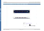
The 4D Button Board for the 4DCAPE is a small PCB 
with  a  row  of  7  momentary  push  buttons  on  the 
front,  and  a  10  way  FFC  connector  designed  for  a 
10-way ribbon cable to attach to, and then connect 
to the 4DCAPE Adaptor board.


The 10 way FFC connectors for the 4D Button Board 
are Bottom Contact, meaning the terminals need to 
be towards the PCB, and the stiffener needs to be 
facing  upwards  (opposite  to  the  main  30  way  FFC 
cable to the display).


8.


Power Source for 4D CAPE 

 
The 4DCAPE power source comes from the BBB, via 
the 4D CAPE Adaptor board which plugs on top of 
the BBB itself. 
 
The Adaptor board taps into the VDD_5V bus power 
on  the  BBB,  which  is  connected  to  the  DC  Barrel 
Jack on the BBB. 

It will not receive power when the 

BBB is powered from USB

, as the USB power goes 

via  the  BBB  power  management  IC,  which  then  is 
supplied on the SYS_5V bus.  
 
It  has  been  designed  this  way  by  default  as  the 
SYS_5V  system  has  finite  capabilities,  and 
depending  what  else  the  BBB  is  doing  and  what 
other CAPES/Devices are connected, there may not 
be sufficient power left to supply the 4DCAPE. Also, 
if a SB (Super Bright) version of the 4DCAPE is used, 
it is very likely the USB power management system 
would  not  supply  enough  power  even  if  nothing 
else  was  connected.  It  however  is  possible  to 
modify  the  4DCAPE  Adaptor  board  to  use  the 
SYS_5V bus, if required. 
On  the  top  of  the  4DCAPE  Adaptor  is  a  Solder 
Jumper,  which  has  3  pads.  By  default,  there  is  a 
track connecting the centre pad to the side marked 
VDD_5V.  If  SYS_5V  is  required  instead,  then  this 

VDD_5V track must be cut between these 2 pads, 
and  a  solder  blob  be  added  instead  between  the 
centre  pad  and  the  pad  marked  SYS_5V.  DO  NOT 
have  both  sides  connected  to  the  centre  pad  at 
once, else your BBB may be damaged.  
 
A sharp craft knife, a soldering iron and solder are 
required ideally for this modification. 
 
Take  care  when  doing  this  modification,  as 
warranty claims will not apply due to damage of the 
product while undertaking this modification. 


9.


Display Module Part Numbers 

 
The following is a breakdown on the part numbers 
and what they mean. 
 

Example:  

gen4-4DCAPE-70CT-SB 
 
gen4 


- gen4 Display Range 


4DCAPE   

- Display Family 

70 


Display size (7.0”)


- Resistive Touch. 

CT 


- Capacitive Touch (with CLB) 

SB 


- Super Bright Display 


For part numbers which do not include T or CT, 
these are non-touch variants. 


Cover Lens Bezels (CLB) are glass fronts for the 
display module with overhanging edges, which 
allow  the  display  module  to  be  mounted 
directly into a panel using special adhesive on 
the overhanging glass. These are available for 
Capacitive Touch only. 


10.


Cover Lens Bezel 

 Tape Spec 

 
The perimeter of the CLB display modules features 
double-sided  adhesive  tape,  designed  to  stick 
directly  onto  a  panel,  enclosure,  box  etc  without 
the need for any mounting screws or hardware. 
 
The tape used is 3M 9495LE tape, which  uses the 
well-known and strong 3M 300LSE adhesive. 
 
The  double-sided  adhesive  has  a  thickness  of 
0.17mm once the backing has been removed. 
 
More information on this adhesive can be found on 
the 3M website. 

http://multimedia.3m.com/mws/media/771683O/
3mtm-double-coated-tapes-9474le-9495le.pdf


Summary of Contents for Gen4 LCD CAPE Series

Page 1: ...PE 43 4 3 Non Touch GEN4 4DCAPE 43T 4 3 Resistive Touch GEN4 4DCAPE 43CT 4 3 Capacitive Touch GEN4 4DCAPE 50 5 0 Non Touch GEN4 4DCAPE 50T 5 0 Resistive Touch GEN4 4DCAPE 50CT 5 0 Capacitive Touch GEN4 4DCAPE 70 7 0 Non Touch GEN4 4DCAPE 70T 7 0 Resistive Touch GEN4 4DCAPE 70CT 7 0 Capacitive Touch GEN4 4DCAPE xxx SB Super Bright All sizes Touch Document Date 8th March 2017 Document Revision 1 0 D...

Page 2: ...s 8 12 Software Driver Disclaimer 8 13 Notes 8 14 Schematic Diagram 4D CAPE 9 15 Schematic Diagram 4DCAPE Adaptor 10 16 Schematic Diagram 4DCAPE Button Board OPTIONAL 11 17 Mechanical Details 4 3 Non Touch Resistive Touch 12 18 Mechanical Details 4 3 Capacitive Touch 13 19 Mechanical Details 5 0 Non Touch Resistive Touch 14 20 Mechanical Details 5 0 Capacitive Touch 15 21 Mechanical Details 7 0 No...

Page 3: ...26 Hardware Revision History 4D CAPE 22 27 Hardware Revision History 4D CAPE Adaptor 22 28 Ordering Information 23 29 Legal Notice 24 30 Contact Information 24 ...

Page 4: ... provided from the BBB directly via the Adaptor and FFC ribbon cable The gen4 LCD CAPE features an optional push buttons connector providing capability for an external button board Please contact Sales regarding this item it is a special order item only Mounting of the 4DCAPE is achieved with the 4x 4mm mounting holes present on the Display Module Resistive and Non Touch enabling standard screws t...

Page 5: ...ower via the DC Jack as the on board power management of the BBB may be overloaded depending on other systems installed So the USB jack will not supply power to the 4D CAPE unless the Solder Bridge jumper on the top of the 4DCAPE Adaptor board is cut and resoldered Discussed further in a later section 7 Once power is connected something should be displayed on the 4DCAPE a few moments after it has ...

Page 6: ... Schematic Diagram for more information about its connections The 4DCAPE also features the TI TPS61165 backlight drive IC which implements a 1 wire communications protocol between the BBB and the Driver IC enabling software commands to be sent from the BBB rather than PWM signals to vary the backlight brightness This results in lower noise and a more stable backlight system A Driver for this is su...

Page 7: ...ement system would not supply enough power even if nothing else was connected It however is possible to modify the 4DCAPE Adaptor board to use the SYS_5V bus if required On the top of the 4DCAPE Adaptor is a Solder Jumper which has 3 pads By default there is a track connecting the centre pad to the side marked VDD_5V If SYS_5V is required instead then this VDD_5V track must be cut between these 2 ...

Page 8: ...____________________________________________________________ __________________________________________________________________________________________ __________________________________________________________________________________________ __________________________________________________________________________________________ __________________________________________________________________...

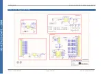
Page 9: ...4D SYSTEMS GEN4 LCD CAPES BEAGLE BONE BLACK 2017 4D SYSTEMS Page 9 of 24 www 4dsystems com au 14 Schematic Diagram 4D CAPE ...

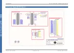
Page 10: ...4D SYSTEMS GEN4 LCD CAPES BEAGLE BONE BLACK 2017 4D SYSTEMS Page 10 of 24 www 4dsystems com au 15 Schematic Diagram 4DCAPE Adaptor ...

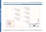
Page 11: ...4D SYSTEMS GEN4 LCD CAPES BEAGLE BONE BLACK 2017 4D SYSTEMS Page 11 of 24 www 4dsystems com au 16 Schematic Diagram 4DCAPE Button Board OPTIONAL ...

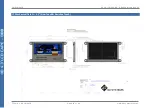
Page 12: ...4D SYSTEMS GEN4 LCD CAPES BEAGLE BONE BLACK 2017 4D SYSTEMS Page 12 of 24 www 4dsystems com au 17 Mechanical Details 4 3 Non Touch Resistive Touch ...

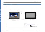
Page 13: ...4D SYSTEMS GEN4 LCD CAPES BEAGLE BONE BLACK 2017 4D SYSTEMS Page 13 of 24 www 4dsystems com au 18 Mechanical Details 4 3 Capacitive Touch ...

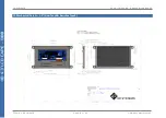
Page 14: ...4D SYSTEMS GEN4 LCD CAPES BEAGLE BONE BLACK 2017 4D SYSTEMS Page 14 of 24 www 4dsystems com au 19 Mechanical Details 5 0 Non Touch Resistive Touch ...

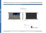
Page 15: ...4D SYSTEMS GEN4 LCD CAPES BEAGLE BONE BLACK 2017 4D SYSTEMS Page 15 of 24 www 4dsystems com au 20 Mechanical Details 5 0 Capacitive Touch ...

Page 16: ...4D SYSTEMS GEN4 LCD CAPES BEAGLE BONE BLACK 2017 4D SYSTEMS Page 16 of 24 www 4dsystems com au 21 Mechanical Details 7 0 Non Touch Resistive Touch ...

Page 17: ...4D SYSTEMS GEN4 LCD CAPES BEAGLE BONE BLACK 2017 4D SYSTEMS Page 17 of 24 www 4dsystems com au 22 Mechanical Details 7 0 Capacitive Touch ...

Page 18: ...4D SYSTEMS GEN4 LCD CAPES BEAGLE BONE BLACK 2017 4D SYSTEMS Page 18 of 24 www 4dsystems com au 23 Mechanical Details 4DCAPE Adaptor ...

Page 19: ...4D SYSTEMS GEN4 LCD CAPES BEAGLE BONE BLACK 2017 4D SYSTEMS Page 19 of 24 www 4dsystems com au 24 Mechanical Details 4DCAPE Button Board OPTIONAL BUILT ON REQUEST ONLY ...

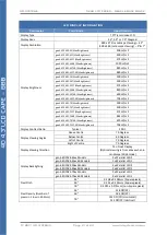
Page 20: ...tness 700 mA gen4 4DCAPE 43CT SB Max Brightness 720 mA gen4 4DCAPE 50 Max Brightness 700 mA gen4 4DCAPE 50T Max Brightness 710 mA gen4 4DCAPE 50CT Max Brightness 720 mA gen4 4DCAPE 50 SB Max Brightness 830 mA gen4 4DCAPE 50T SB Max Brightness 840 mA gen4 4DCAPE 50CT SB Max Brightness 850 mA gen4 4DCAPE 70 Max Brightness 980 mA gen4 4DCAPE 70T Max Brightness 990 mA gen4 4DCAPE 70CT Max Brightness 1...

Page 21: ...APE 70 Max Brightness 500 cd m2 gen4 4DCAPE 70T Max Brightness 400 cd m2 gen4 4DCAPE 70CT Max Brightness 475 cd m2 gen4 4DCAPE 70 SB Max Brightness 844 cd m2 gen4 4DCAPE 70T SB Max Brightness 679 cd m2 gen4 4DCAPE 70CT SB Max Brightness 758 cd m2 Display Contrast Ratio Typical 500 1 Display Viewing Angles Above Centre 70 Degrees Below Centre 60 Degrees Left of Centre 70 Degrees Right of Centre 70 ...

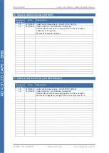
Page 22: ...3 MODEL 2 1 23 11 2016 Updated Version For All Models including SB Fixed bottleneck with power supply apparent on 5 0 and higher Added local 3 3V regulator Removed FET Polarity Protection Revision Number Date Description 1 0 28 10 2016 Initial Public Release Version ONLY FOR 4 3 MODEL 2 0 23 11 2016 Updated Version For All Models including SB Fixed bottleneck with power supply apparent on 5 0 and ...

Page 23: ...er Code GEN4 4DCAPE 43 Non Touch GEN4 4DCAPE 43T Resistive Touch GEN4 4DCAPE 43CT Capacitive Touch GEN4 4DCAPE 50 Non Touch GEN4 4DCAPE 50T Resistive Touch GEN4 4DCAPE 50CT Capacitive Touch GEN4 4DCAPE 70 Non Touch GEN4 4DCAPE 70T Resistive Touch GEN4 4DCAPE 70CT Capacitive Touch Packaging Module sealed in antistatic foam padded 4D Systems Box ...

Page 24: ...ages and graphics used are possible to be displayed on the 4D Systems range of products however the quality may vary In no event shall 4D Systems be liable to the buyer or to any third party for any indirect incidental special consequential punitive or exemplary damages including without limitation lost profits lost savings or loss of business opportunity arising out of or relating to any product ...

Reviews: