3xLogic VX-2V-MD-RIWH Quick Start Manual Download Page 17

V-Series Camera Quick Start Guide |


VX-2V-MD-RIWH


12000 Pecos St., Suite 290, Westminster, CO 80234 | www.3xlogic.com | (877) 3XLOGIC


17 

3


Quick Start 


Quick Start - Enabling HDMI Output in Camera Browser Settings for Public View 

Monitor Use 

To utilize the camera’s HDMI output for use with an external monitor, confirm the camera’s Local Output 
display settings is configured correct.   


Steps: 

1.


Navigate to the camera’s web interface login screen.  

2.


Enter the camera’s IP address into a browser URL field and hit 

Enter

. Fill in the required login credentials 

and click 

Login

 to proceed. 


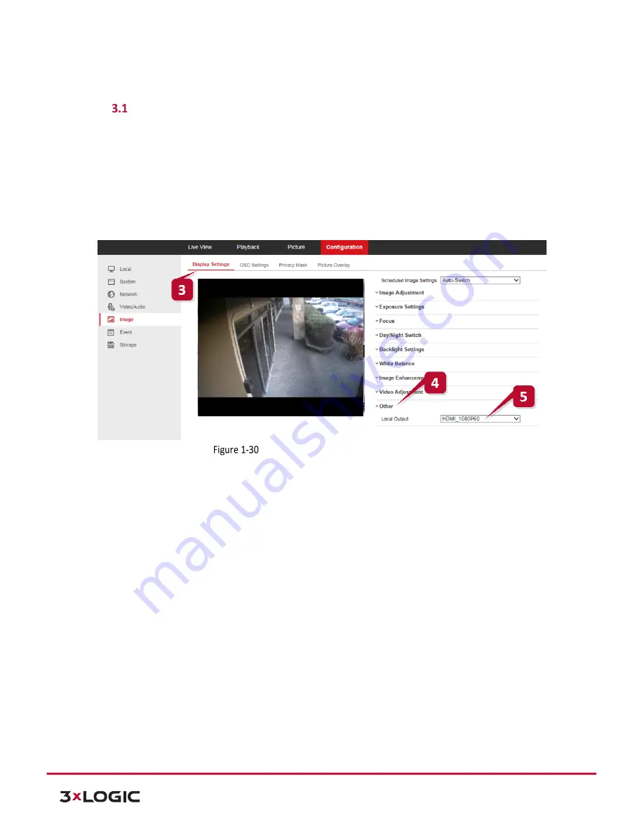
Enabling HDMI Output in Browser Settings 

3.


Navigate to 

Configuration>Image>Display Settings.


4.


Click 

Other 

to deploy the 

Local Output

 settings menu.  

5.


Select 

HDMI_1080P60


Summary of Contents for VX-2V-MD-RIWH

Page 1: ...Series Camera Quick Start Guide VX 2V MD RIWH 12000 Pecos St Suite 290 Westminster CO 80234 www 3xlogic com 877 3XLOGIC 1 VISIX V Series All in One Camera Gen II VX 2V MD RIWH Quick Start Guide v01 20...

Page 2: ...Mouting 10 Optional Installation of Network Cable Water Proof Jacket 12 Optional Installation of Waterproof Tape 12 2 CAMERA SETUP 15 AVAILABLE CAMERA SETUP TOOLS 15 CAMERA SETUP DHCP ENABLED NETWORK...

Page 3: ...cription D2 Wall Mount 3xLOGIC Product VX WM D2 D2 Pendant Mount 3xLOGIC Product VX PM D2 D2 Ceiling Flush Mount 3xLOGIC Product VX FM D2 Universal Corner Mount 3xLOGIC Product VX CM Universal Pole Mo...

Page 4: ...enough to withstand four times the weight of the camera and the bracket For the camera that supports IR you are required to pay attention to the following precautions to prevent IR reflection n Dust...

Page 5: ...body to completely expose the memory card slot 2 Insert the memory card into the memory card slot and push it in to mount the card Memory Card Install the Memory Card 3 Optional To unmount the memory...

Page 6: ...amera models n Optional Routing the cable from the side outlet instead of the cable hole drilled on the ceiling is supported Side Outlet Side Outlet 3 Fix the mounting base to the ceiling with the sup...

Page 7: ...lt 0 to 75 Pan 0 to 355 Rotate 0 to 355 3 axis Adjustment 7 Zoom and Focus Adjustment Cameras of this series are equipped with a motor driven lens You can adjust the zoom and focus level on PTZ contro...

Page 8: ...9 Tighten the lock screw to complete the installation Lock Screw Complete the Installation INSTALLATION WALL MOUNTING Before you start A wall mounting bracket is not included in package If you choose...

Page 9: ...ll the wall mounting bracket and secure the cap on the bracket Wall Mounting Bracket Cap Install Wall Mounting Bracket 2 Align the screw holes of the mounting base with the corresponding screw holes o...

Page 10: ...us 7 Install the dome cover back to the camera and tighten the lock screw to complete the installation INSTALLATION PENDANT MOUTING Before you start The Pendant mounting bracket is not included in pac...

Page 11: ...ng base with the corresponding screw holes of the cap Cap Mounting Base Install the Mounting Base 3 Secure the mounting base to the cap with screws 4 Align the camera with the mounting base and secure...

Page 12: ...rubber gasket the rubber gasket inset ridge must face the waterproof endcap and the waterproof endcap in order 2 Crimp an RJ 45 network plug onto the end of the cable taking care to insert the twisted...

Page 13: ...etch Stretch Initial Length Waterproof Tape Length After Stretching Stretch the Water proof Tape 3 Wrap the water proof tape around the cable connector tightly as shown in the figure below Cable Conne...

Page 14: ...ww 3xlogic com 877 3XLOGIC 14 Wrap the Water proof Tape Note Make sure that all exposed wires are all firmly wrapped and concealed by the water proof tape 6 Press the tape firmly to make sure no water...

Page 15: ...ended 1 Ensure the connected network provides a DHCP address and allows outbound access to the internet For installations where DHCP is not available or where the camera is being used with an applianc...

Page 16: ...To activate the camera you will be required to assign a complex password 7 Confirm the camera Live View preview is as desired and click Continue 8 Adjust any all camera settings including the camera...

Page 17: ...use with an external monitor confirm the camera s Local Output display settings is configured correct Steps 1 Navigate to the camera s web interface login screen 2 Enter the camera s IP address into a...

Page 18: ...itional network connection criteria IP Port 5 Click Test VIGIL Connect to confirm the camera can be communicated with through the Connect system using the provided alias Skip this step if using tradit...

Page 19: ...VIGIL Server within View Lite II The VIGIL Server window will now deploy A menu of all VIGIL Servers already interfaced with View Lite II will be visible Adding a Video Source Add Video Source 4 To a...

Page 20: ...3xLOGIC www 3xlogic com 2018 3xLOGIC Inc All rights reserved Information in this document is subject to change without notice 3xLOGIC and the 3xLOGIC logo are trademarks of 3xLOGIC Inc all other trad...

Reviews: