


Chapter 2. Installing Your 3ware RAID Controller
24
3ware 9650SE Serial ATA RAID Controller Installation Guide
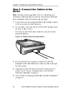
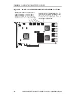
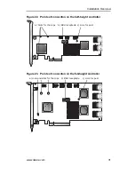
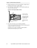
Figure 19. 16-Port 3ware 9650SE-16ML Serial ATA RAID Controller
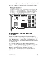
Overall LED drive status indicator is the
right-most LED header pin pair on each
LED connector (J7, J8, J9, J1). The
anode is the lower of the two pins and
the cathode is the upper.
LED indicators for individual drives
J7 is for drives 0, 1, 2, 3 (left to right)
J8 is for drives 4, 5, 6, 7 (left to right)
J9 is for drives 8, 9, 10, 11 (left to right)
J1 is for drives 12, 13, 14, 15 (left to right)


