background image

Step 8:

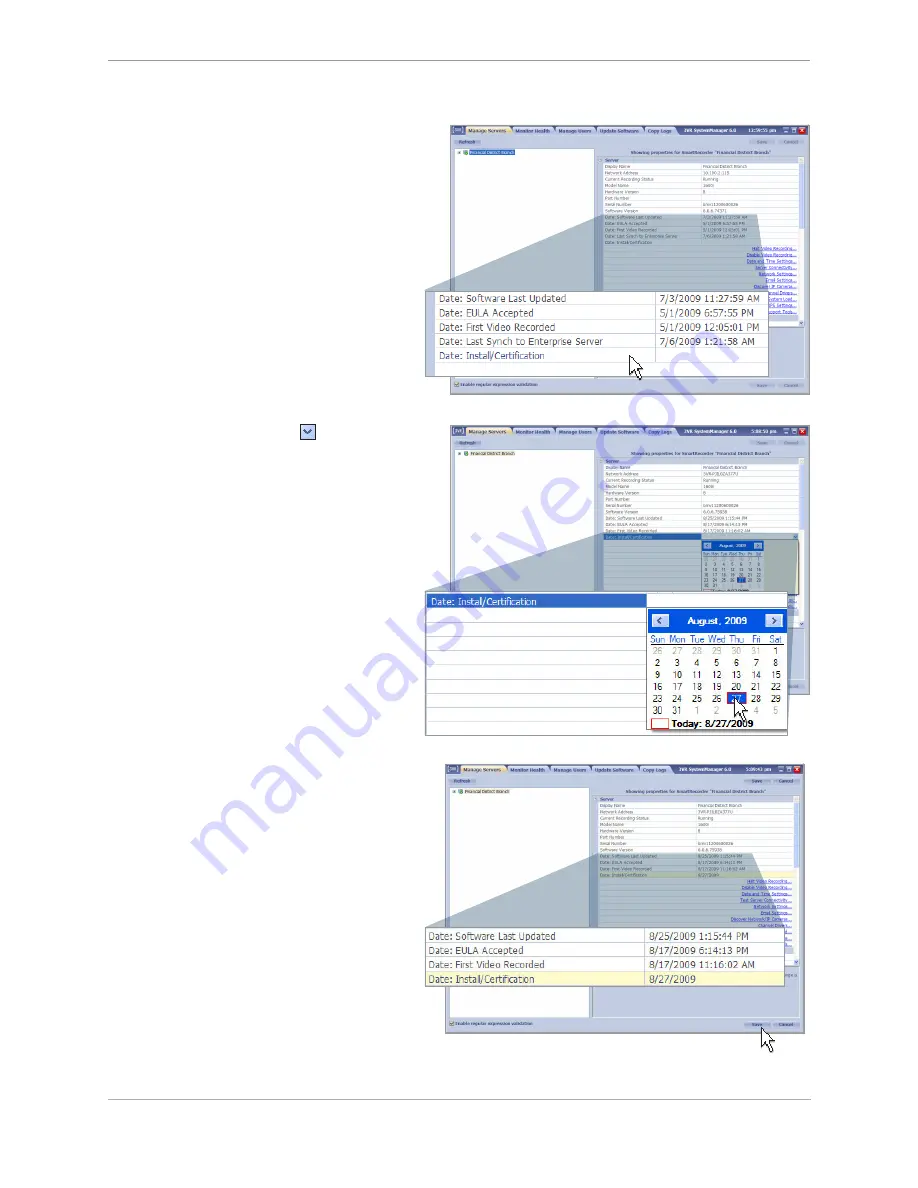
Set Install/Certification Date

When you have finished installing and configuring 
a 3VR SmartRecorder, save the current date in the 
system settings for future reference:

In the 

1. 

Manage Servers 

tab, select the name 

of the SmartRecorder.

In the 

2. 

Server

 settings, locate the 

Date: 

Install/Certification

 field.

Click the dropdown arrow 

3. 

 next to 

Date: 

Install/Certification

 and select today’s date 

from the calendar.

Click 

4. 

Save

.

44

        3VR SmartRecorder Installation and Configuration Guide

Summary of Contents for E-Series SmartRecorder

Page 1: ...Brannan Street Suite 430 San Francisco CA 94107 Tel 415 495 5790 Sales 415 513 4611 Fax 415 495 5797 Email info 3VR com www 3VR com 3VR and the 3VR logo are either trademarks or federally registered...

Page 2: ...nect Analog Cameras 27 Step 9 Verify Video Quality 30 Chapter 2 Configuring a 3VR SmartRecorder Step 1 Configure Channels for Analog Cameras 34 Step 2 Configure Outgoing Email Settings 36 Step 3 Insta...

Page 3: ...of 3VR 3VR may have patents patent applications trademarks copyrights or other intellectual property rights covering subject matter in this document Except as expressly provided in any written licens...

Page 4: ...4...

Page 5: ...Product Diagrams P Series SmartRecorder 6 S Series SmartRecorder 7 E Series SmartRecorder 8 M Series SmartRecorder 9 5...

Page 6: ...ve bay 4 power button USB ports power cable socket fan mouse port unused parallel port external I O port video input ports unused audio input ports keyboard port RS 232 serial port monitor port primar...

Page 7: ...ort monitor port RS 232 serial port USB ports unused parallel port primary Ethernet port SpotMonitor adapter port video input ports digital output port RS 422 485 serial port digital input port power...

Page 8: ...ard drive activity indicator power button reset button power cable socket USB ports Ethernet port video input ports monitor port unused parallel port keyboard port mouse port fan power indicator rack...

Page 9: ...Product Diagrams M Series SmartRecorder Front view Back view Product Diagrams 9...

Page 10: ...10...

Page 11: ...and SmartSearch NVR 18 Step 2 Log In to the SmartRecorder 20 Step 3 Check System Software Version 21 Step 4 Rename the SmartRecorder 22 Step 5 Set the System Time Zone 23 Step 6 Set the System Date a...

Page 12: ...Panel Keyboard Mouse Two Rack mount Ears Alarm Input Output Adapter Installation and Resource CD One or Two Video Cables depends on system configuration The following items should be found in the P S...

Page 13: ...nit Connect the power cable 4 Connect a network cable to the 5 left primary Ethernet port If you will be connecting to the SmartRecorder with a monitor mouse and keyboard Once a suitable location has...

Page 14: ...ur Screws Power Supply The following items will be found in the S Series shipping container 3VR SmartRecorder S Series Installation and Resource CD One or Two Video Cables depends on system configurat...

Page 15: ...imum of 4 clearance in both front and rear of unit To mount the SmartRecorder on a wall 2 attach one wall mount to each side of the SmartRecorder using the included screws Mount the unit as appropriat...

Page 16: ...R SmartRecorder M Series DC to AC Adapter Power Source USB PS 2 adapter Installation and Resource CD The following items will be found in the M Series shipping container M Series SmartRecorder 16 3VR...

Page 17: ...of unit Once a suitable location has been identified mount the unit as appropriate 2 for the installation Connect USB keyboard and mouse to the 5 USB ports or connect a PS 2 keyboard and mouse to the...

Page 18: ...Rack mount Ears Two Four Video Cables depends on system configuration 5 6 7 8 3 4 Front Panel Hinges Front Panel Keyboard Mouse Two Rack mount Ears Two Four Video Cables depends on system configuratio...

Page 19: ...t and rear of unit Connect the keyboard to the purple port 6 and the mouse to the green port Connect a monitor to the monitor port 7 Press the power button on the front of 8 the unit If you will be co...

Page 20: ...he first time a SmartRecorder is powered on 1 the End User License Agreement screen will be displayed To accept the terms of the agreement check the box beside I have read and agree and click Accept A...

Page 21: ...en the name of the SmartRecorder is highlighted the current software build is displayed in the Software Version field If necessary upgrade the software on your SmartRecorder using the instructions in...

Page 22: ...anager 1 From the 2 Manage Servers tab click the name currently assigned to the SmartRecorder Information about the SmartRecorder will be displayed to the right Click the 3 Display Name field and edit...

Page 23: ...choose the time zone where the SmartRecorder will be located from the dropdown list Under the 2 Server category heading click Date and Time Settings Click 4 Save to save your changes Click 5 OK in th...

Page 24: ...r to automatically set the date and time select Automatically set time from a remote server and type in the NTP server address To set the time manually click Manually set date and time and set the cur...

Page 25: ...Manage Servers tab of SystemManager select the SmartRecorder name Information about the system will appear to the right details E Series and S Series SmartRecorders will only show one network adapter...

Page 26: ...e known host a health alert will be generated troubleshooting If you experience difficulty in connecting to the network contact the customer s IT department to verify the network port is enabled To as...

Page 27: ...channel units Fasten the yellow video input cable to port A 1 in the diagram above Connect cameras 1 16 to the BNC connectors 2 24 and 32 channel units Fasten the second yellow video input cable to 3...

Page 28: ...ill only have one video input port and one video cable included in the shipping container Connect the video input cable to the 1 Video In port on the back of the unit Connect cameras to the BNC connec...

Page 29: ...nnel dongle has two extra connectors with black and white wires labeled AID 1 and AID 2 Do not connect cameras to connectors AID 1 and AID 2 Use the video input dongles to connect the analog camera fe...

Page 30: ...martRecorder name and select Watch Video On Server When the live video panel loads all of the enabled channels will be selected automatically Step 9 Verify Video Quality Verify video quality on all en...

Page 31: ...Chapter 1 Installing a 3VR SmartRecorder 31...

Page 32: ...32...

Page 33: ...Step 4 Configure Event and Video Storage Settings 39 Step 5 Define the Schedule for Recording Settings 40 Step 6 Define the Schedule for Bandwidth Control 41 Step 7 Enter System License Keys Optional...

Page 34: ...g C25 Unlicensed and disabled to avoid licensing fees Step 1 Configure Channels for Analog Cameras To modify a channel s settings click the channel 3 name to highlight it Details about the channel wi...

Page 35: ...hannel to be disabled 1 Under the 2 Channel Description category heading click Disable Channel Edit the channel name to indicate why it is 3 disabled If the channel is licensed but unused type Unused...

Page 36: ...is required for email append the port number to the IP address or mail server name in this field using this format mail yourcompany com 123 3VR SmartRecorder Email Address Enter the email address tha...

Page 37: ...box click Install to proceed Navigate to the folder containing the plug in 4 file Select the file and click 5 OK The plug in will now begin installing note If the plug in file is not visible in its c...

Page 38: ...in documentation Restart the SmartRecorder by right clicking the 8 SmartRecorder name and selecting Restart Server In the 9 Confirm dialog box click Reboot to initiate the server restart Close System...

Page 39: ...ents for the specified duration these values may be overridden The 3VR SmartRecorder can retain optimized images and event information for extended periods of time if video has been removed from the s...

Page 40: ...box 3 representing the start time drag the mouse to the right and release when the continuously highlighted region represents the full range of peak hours The unselected time range represents off pea...

Page 41: ...k hours The unselected time range represents off peak hours To revert to the previously stored settings click Restore All To clear the selection for a single day of the week click the to the right of...

Page 42: ...ve your changes To configure maximum bandwidth values click the 9 next to Maximum Bandwidth Enter the maximum allowed bandwidth for Peak and 10 Off Peak hours and click Save to permanently store the v...

Page 43: ...ab select the server name Click 2 License Settings Click 3 Add Update License Key Enter the key in the resulting dialog box 4 Click the 5 Add Update License Key button When you return to the 6 License...

Page 44: ...em settings for future reference In the 1 Manage Servers tab select the name of the SmartRecorder In the 2 Server settings locate the Date Install Certification field Click the dropdown arrow 3 next t...

Page 45: ...ervers tab of SystemManager click the next to Plug ins Click 2 3VR Installation Report Application note If 3VR Installation Report Application does not appear in the list of plug Ins contact 3VR Techn...

Page 46: ...ort preview for accuracy 7 To go back and make changes click Edit To save the preview on your computer as an HTML file click Save and navigate to the location where you wish to save the report To emai...

Page 47: ...Chapter 2 Configuring a 3VR SmartRecorder 47...

Page 48: ......

Page 49: ...ite 430 San Francisco CA 94107 Tel 415 495 5790 Sales 415 513 4611 Fax 415 495 5797 Email info 3VR com www 3VR com 3VR and the 3VR logo are either trademarks or federally registered trademarks of 3VR...

Page 50: ...will examine and explain the many elements that are critical to using 3VR for facial surveillance While fundamental principles apply to images from photographic cameras as well as CCTV cameras the ap...

Page 51: ...l cited is 640 x 480 pixels This means that there are 640 unique pixels across the image horizontally and 480 pixels down the image vertically The number of horizontal pixels is important for performi...

Page 52: ...emingly minor difference we shall show later how this makes a significant dif ference on the suitability of the images for facial analysis An image does not have a singular width for the field of view...

Page 53: ...can capture faces in a field of view FOV no more than about 4 5 feet Rule of thumb place a person standing in the foreground in optimal focus When they hold their arms stretched out from side to side...

Page 54: ...s need to be mounted low enough or far away enough so that the vertical angle or slope does not exceed 20 above the eye level when subjects are in focus in the foreground Given an aver age eye height...

Page 55: ...l pixels is still the key factor in terms of performing 3VR facial surveillance the advan tage can be noted in the table below 1024 x 768 0 7 6 5 1280 x 1024 1 3 8 0 1600 x 1200 2 10 5 2048 x 1536 3 1...

Page 56: ...areas within the face and lots of detail is visible Photo B Overexposed There are no areas of shadow but there are significant areas with glare notice the cheeks nose and forehead There is a narrower...

Page 57: ...ify and set appropriate expectations Video from DVRs are often recorded at resolutions lower than 4CIF such as 2CIF or CIF Because of the reduction of resolution the field of view needed for sufficien...

Page 58: ...e cameras positioned so the lines of sight slightly overlap The degree of over lap should enable each camera to capture the full face of a subject who passes halfway between them instead of each camer...

Page 59: ...t of 5 and a maximum vertical slope of 20 D Distance to Subject 10 15 20 25 30 2 D 20 of Distance to Subject 2 3 4 5 6 E Eye Height 5 5 5 5 5 H Max Mounting Height 7 8 9 10 11 Simple Formula Multiply...

Page 60: ...t Lens Selection Typical VariFocal Lenses fall within the following approximate ranges 3 to 8 millimeters mm 3 to 12mm 5 to 50mm and 20 to 100mm The most common and least expensive are the 3 to 8mm ve...

Page 61: ...le Rule of thumb The image must simultaneously show both ears of the subject 5 Lighting High quality required with wide dynamic range Well lit no harsh shadows or glare 6 Event Length There must be a...

Page 62: ...age 2 The person s face must look directly towards the camera This affects both the class of imported pho tos that are acceptable and how video cameras must be positioned to capture faces 3 Imported i...

Page 63: ...curity Inc 475 Brannan Street Suite 430 San Francisco CA 94107 Tel 415 495 5790 Sales 415 513 4611 Fax 415 495 5797 Email info 3VR com www 3VR com 3VR and the 3VR logo are either trademarks or federal...

Page 64: ...r third party firewalls and all virus adware or spyware detection software running on 3 the laptop Plug the USB Network Service Adapter into a USB port on the 3VR system 4 Connect an Ethernet cable fr...

Page 65: ...Network Service Adapter may assign a new 169 254 xxx xxx address for the SmartRecorder each time the server is restarted Click the 10 Find Local Server button The first time a SmartRecorder is powered...

Page 66: ...any Windows or third party firewalls and all virus adware or spyware detection software running on 3 the laptop Connect an Ethernet cable from the laptop Ethernet port to the secondary port on the 3VR...

Page 67: ...SmartRecorder is powered on 11 the End User License Agreement screen will be displayed To accept the terms of the agreement check the box beside I have read and agree and click Accept When the laptop...

Page 68: ...3VR Security Inc 475 Brannan Street Suite 430 San Francisco CA 94107 Tel 415 495 5790 Sales 415 513 4611 Fax 415 495 5797 Email info 3VR com www 3VR com 3VR and the 3VR logo are either trademarks or...

Page 69: ...at the bottom of the window Close SystemManager 7 Click 3 Browse In the 4 Choose 3VR Update File window locate the update file ending in the extension 3pa and click OK Click 2 Inspect Under the Status...

Reviews: