


Provide 4-bit DIP switch for function setting,
where "ON" is enable valid terminal. Please
power off and power on after changing the status
of DIP switch. DIP switch definition as follow:
DIP
Decscription
Operation
1
Reserved
—
2
Restore factory
setting
Set the switch to ON, power on
again, it restores to factory
defaults, set the switch back.
3
Reserved
—
4
Reserved
—
【
Serial Port Connection
】
RS232 and 3IN1 RJ45 interface
Model I, Model II, Model III, and Model IV
provide 3IN1 serial port that supports
RS-232/485/422. The interface is RJ45; Model
V, Model VI, Model VII, and Model VIII support
RS-232. The interface is RJ45.
The RJ45 PIN definitions are as follows.
PIN
1
2
3
4
5
6
7
8
RS-232
DSR RTS GND TXD RXD DCD CTS DTR
RS-485
—
—
GND —
—
D-
—
D+
RS-422
—
R-
GND R+
—
T-
—
T+
RS-485/422 Port
Model IX, Model X, Model XI, and Model
XII provide 5-pin 5.08mm pitch industrial
terminal block. The PIN definitions are as
follows.
PIN
1
2
3
4
5
RS-422
T+
T-
GND
R+
R-
RS-485
D+
D-
GND
—
—
【
Checking LED Indicator
】
The device provides LED indicators to monitor the device
working status with a comprehensive simplified
troubleshooting; the function of each LED is described in the
table as below:
LED
Indicate Description
PWR
ON
The power connection is working
normally.
OFF
The power is not connected or is
not working normally.
RUN
ON
The system is not running
normally.
Blinking The system is running normally.
OFF
The system is not running or
running abnormally.
LINK (1-2)
ON
The LAN interface has established
an active network connection.
Blinking
The LAN interface is in an active
network state.
OFF
The LAN interface has not
established an active network
connection.
TX
Port(1-4/8)
OFF
No data or abnormal data is being
received through serial port.
Blinking Serial port is receiving data.
RX
Port(1-4/8)
OFF
No data or abnormal data is being
transmitted through serial port.
Blinking Serial port is transmitting data.
【
Logging in to WEB Interface
】
This device supports WEB management and configuration.
Computer can access the device via Ethernet interface. The
way of logging in to device’s configuration interface via IE
browser is shown as below:
Note
Single-port and double-port products have different
configuration. Please note the single and double port identifier in
front of the steps.
Single-port product: Model I, Model III, Model V,
Model VII, Model I
Ⅹ
and Model XI.
Double-port product
:
Model II, Model IV, Model VI,
Model VIII, Model
Ⅹ
and Model
Ⅹ
II.
Step 1
(Single port) Configure the IP addresses of
computer and the device to the same network
segment, and the network between them can be
mutually accessed.
Step 2
(Double port) Configure the IP addresses of
computer and the device to the same network
segment(The network segment of Network Port 1 is
1, and the network segment of network port 2 is 8),
and the network between them can be mutually
accessed.
Step 3
(Single port)Enter device’s IP address in the
address bar of the computer browser.
Port1
:
Step 4
(Double port)Enter device’s IP address in the
address bar of the computer browser.
Port1
:
Port 2
:
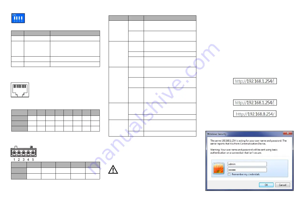
Step 5
Enter device’s username and password in the login
window as shown below.
Step 6
Click “OK” button to login to the WEB interface of
the device.
1
8


