


Power input voltage of model VI model VIIand model X:
48VDC, power input voltage of model I and model III: 48VDC
(12~48VDC).
AC power supply 220VAC
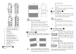
This series of model II and model IV
support AC single power supply and
provide 6 pins 5.08mm pitch input
terminal blocks, including 4 pins power supply terminal blocks
on the left side.
Power input voltage: 220VAC (85~264VAC).
【
Relay Connection
】
The device provides 6-pin 5.08mm pitch
input terminal blocks , including 2-pin
relay terminal blocks on the right side.
Relay terminals are a pair of normally
open contacts in device alarm relay.
They are open circuit in normal non alarm state, closed when
any alarm information occurs. Such as: it's closed when power
off, and send out alarm. The switch supports 1 channel relay
alarm information output, support DC power alarm information
or network abnormal alarm output, it can be connected to
alerting lamp, alarm buzzer, or other switching value collecting
devices for timely warning operating staffs when alarm
information occurs.
【
DIP Switch Settings
】
Provide 4 pins DIP switch for function settings,
where "ON" is enable valid terminal. Please
power off and power on after changing the status
of DIP switch. DIP switch definition as follows:
DIP
Definition
Operation
1
Restore
factory
defaults
Set the DIP switch to ON, power
on the device again, it will
restore to factory settings, then
turn off the DIP switch.
2
Reserved
-
3
Upgrade
Set the DIP switch to ON, the
program of this device can be
DIP
Definition
Operation
upgraded, then turn off the DIP
switch
when
this
upgrade
completes.
4
Reserved
-
【
Console Port Connection
】
The device provides 1 channel procedure debugging port
based on serial port, and can conduct device CLI command
line management after connected to PC. The interface adopts
RJ45 port, the RJ45 pin definition is as follows:
Pin No.
2
3
5
Definition
TXD
RXD
GND
【
Checking LED Indicator
】
The function of each LED is described in the table as below:
LED
Status
Description
P1/P2/PWR
ON
Power supply is connected
and running normally
OFF
Power supply is
disconnected and running
abnormally.
ALM
ON
Power supply, port link
alarm
OFF
Power supply, port link
without alarm
RUN
ON
The device is powered on or
the device is abnormal.
OFF
The device is powered off or
the device is abnormal.
Blinking
System is running well.
Link/ACT
(1-4/8, G1-G2)
ON
Ethernet port connection is
active.
Blinking
Data transmitted
OFF
Ethernet port connection is
inactive.
POE (1-4/8)
ON
POE port supply electricity
for other devices normally
OFF
POE is disabled or
disconnected
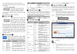
【
Logging in to WEB Interface
】
This device supports WEB management and configuration.
Computer can access the device via Ethernet interface. The
way of logging in to device
’s configuration interface via IE
browser is shown as below:
Configure the IP addresses of computer and the
Step 1
device to the same network segment, and the
network between them can be mutually accessed.
Enter device
’s IP address in the address bar of the
Step 2
computer browser.
Enter device
’s username and password in the login
Step 3
window as shown below.
Click
“OK” button to login to the WEB interface of
Step 4
the device.
Note:
The default IP address of the device is “192.168.1.254”.
The default username and password of the device is
“admin”.
If the username or password is lost, user can restore it to
factory settings via device DIP switch or management
software; all modified configurations will be cleared


