
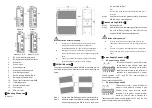


Model III Model I
Model VIII, IX,X Model V, VI,VII
1.
DC power input terminal block
2.
Relay alarm output terminal block
3.
DIP switch
4.
Console port
5.
Grounding screw
6.
Wall-mounted location hole
7.
DIN-Rail mounting kit
8.
Device running indicator RUN
9.
Relay alarm indicator ALM
10.
Power input status indicator PWR
11.
100M copper port
12.
Ethernet port indicator
13.
Combo port
14.
POE indicator
【
Mounting Dimension
】
Unit: mm
Attention before mounting:
Don't place or install the device in area near water or
moist, keep the relative humidity of the device
surrounding between 5%~95% without condensation.
Before power on, first confirm the supported power
supply specification to avoid over-voltage damaging the
device.
The device surface temperature is high after running;
please don't directly contact to avoid scalding.
【
DIN-Rail Mounting
】
The product adopts 35mm standard DIN-Rail mounting, which
is suitable for most of the industrial scenes. Mounting steps as
below:
Check if the DIN-Rail mounting kit is installed firmly.
Step 1
Insert the bottom of DIN-Rail mounting kit (one side
Step 2
with spring support) into DIN-Rail, and then insert
the top into DIN-Rail.
Tips:
Insert a little to the bottom, lift upward and then insert
to the top.
Check and confirm the product is firmly installed on
Step 3
DIN-Rail, then mounting ends.
【
Disassembling DIN-Rail
】
Device power off.
Step 1
After lift the device upward slightly, first shift out the
Step 2
top of DIN-Rail mounting kit, then shift out the
bottom of DIN-Rail, disassembling ends.
Notes before power on:
Power ON operation: first connect power line to the
connection terminal of device power supply, then power
on.
Power OFF operation: first unpin the power plug, then
remove the power line, please note the operation order
above.
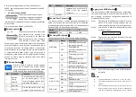
【
Power Supply Connection
】
DC power supply 24VDC
This series of model V, model VIII, model
IX pro vide 6 pins 5.08mm pitch input
terminal blocks , including 4 pins power
supply terminal blocks on the left side. It
provides two independent DC power
supply systems of P1 and P2. The power supply is
anti-reverse connection.
Power input voltage: 24VDC
DC power supply 48VDC
This series of model I, model III, model VI
model VII and model X provide 6 pins
5.08mm pitch input terminal blocks,
including 4 pins power supply terminal
blocks on the left side. It provides two
independent DC power supply systems of P1 and P2. The
power supply is anti-reverse connection.


