


Note:
Don't place or install the device in area near water or moist,
keep the relative humidity of the device surrounding between
5%~95% without condensation.
Before power on, first confirm the supported power supply
specification to avoid over-voltage damaging the device.
The device surface temperature is high after running; please
don't directly contact to avoid scalding.
【
Wall-mounting
】
Step 1
Place the device on the wall of device mounting as
reference or refer to the installation dimension to
mark the position of the two screws.
Step 2
Fix the M4 screw in the wall and reserve 2mm
interspace
Step 3
Hang the device on the two screws and slide
downward, and then tighten the screws, mounting
ends.
【
Disassembling Wall-mounting Device
】
Power off the device.
Step 1
Unscrew the screws in the wall about 2mm.
Step 2
Lift upward the device lightly to remove the device,
Step 3
disassembling ends.
Note:
Power ON operation: First insert the power supply terminal
block into the device power supply interface, and then plug the
power supply socket and power on.
Power OFF operation: First, unpin the power supply plug. And
then remove the connector of the terminal block. Please notice
the operation order above.
【
Power Supply Connection
】
The top panel of CAN232 interface converter
provides 2-pin industrial terminal blocks (DC IN),
thereinto, DC IN is 9~48VDC power supply
input. Power supply supports nonpolarity.
【
DIP Switch Settings
】
4-pin DIP switches are provided for function
settings, among which
“ON” is enabling valid
end.
DIP switches definition as follows:
DIP
Definition
Operation
1
Reserved
-
2
Configuration
mode settings
Dial the DIP to ON, the
converter
enters
into
“configuration” mode after being
powered on;
Dial
down
the
DIP,
the
converter enters into
“normal
operation
” mode after being
powered on.
3
Restore factory
defaults
Dial the DIP to ON, the device
will automatically reboot and
restore factory defaults, dial
back the DIP.
4
Reserved
-
【
CAN Port
】
CAN port of CAN232 adopts 5-pin 5.08mm
pitch terminal blocks.
Pin NO.
Pin Name
Pin Definition
1
GND
Ground wire
2
CANL
Connecting end of CANL
signal line
3
CANH
Connecting end of CANH
signal line
4
RES+
CAN
network
matching
resistor end 1
5
RES-
CAN
network
matching
resistor end 2
Pin 4 is marked with
“Res+” and pin 5 is marked with “Res-”,
which are connected to the terminal resistance of CAN
network. When CAN232 converter serves as CAN-bus
network terminal, two pins are connected by 120 ohms
resistor; otherwise it
’s useless to install 120 ohms resistor.
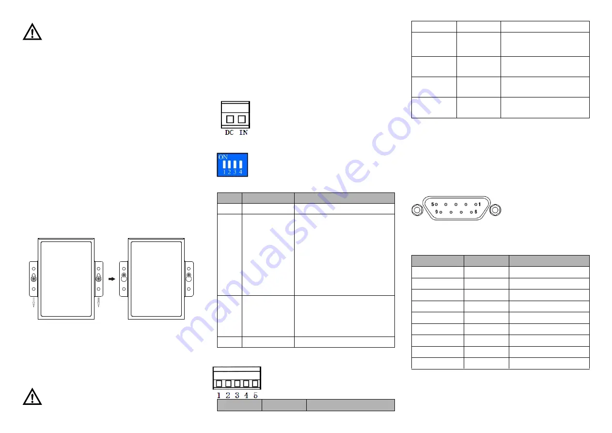
【
RS-232 Serial Port
】
As for the CAN232, RS-232
ports adopt standard DB9
socket,
pin
definition
conforms to RS-232 norm.
Here three-wire connection
is adopted.
RS-232 serial port DB9F
Pin NO.
Pin Name
Pin Definition
1
—
Without connection
2
TxD
Data sending end
3
RxD
Data receiving end
4
—
Without connection
5
GND
Ground wire
6
—
Without connection
7
—
Without connection
8
—
Without connection
9
—
Without connection
【
Checking LED Indicator
】
CAN232 interface converter provides LED indicators to
monitor the device working status with a comprehensive
simplified troubleshooting; the function of each LED is


