background image

11

TECHNICAL

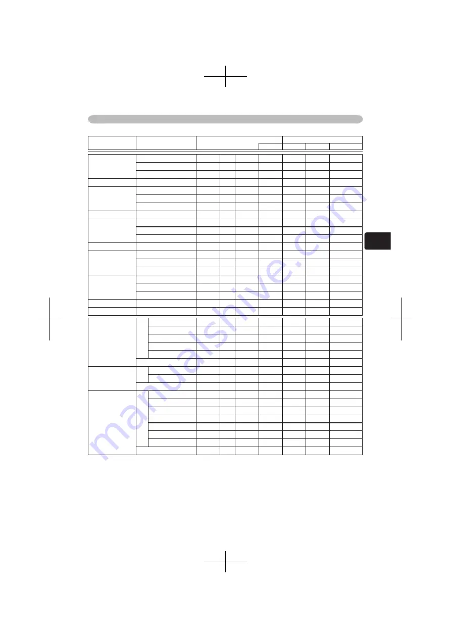
RS-232C Communication (continued)

Names Operation 

Type

Header

Command Data

CRC

Action

Type

Setting Code

OVER SCAN

Get

BE  EF

03

06  00

91  70

02  00

09  22

00  00

Increment

BE  EF

03

06  00

F7  70

04  00

09  22

00  00

Decrement

BE  EF

03

06  00

26  71

05  00

09  22

00  00

OVER SCAN Reset

Execute

BE  EF

03

06  00

EC  D9

06  00

27  70

00  00

V POSITION

Get

BE  EF

03

06  00

0D  83

02  00

00  21

00  00

Increment

BE  EF

03

06  00

6B  83

04  00

00  21

00  00

Decrement

BE  EF

03

06  00

BA  82

05  00

00  21

00  00

V POSITION Reset

Execute

BE  EF

03

06  00

E0  D2

06  00

02  70

00  00

H POSITION

Get

BE  EF

03

06  00

F1  82

02  00

01  21

00  00

Increment

BE  EF

03

06  00

97  82

04  00

01  21

00  00

Decrement

BE  EF

03

06  00

46  83

05  00

01  21

00  00

H POSITION Reset

Execute

BE  EF

03

06  00

1C  D3

06  00

03  70

00  00

H PHASE

Get

BE  EF

03

06  00

49  83

02  00

03  21

00  00

Increment

BE  EF

03

06  00

2F  83

04  00

03  21

00  00

Decrement

BE  EF

03

06  00

FE  82

05  00

03  21

00  00

H SIZE

Get

BE  EF

03

06  00

B5  82

02  00

02  21

00  00

Increment

BE  EF

03

06  00

D3  82

04  00

02  21

00  00

Decrement

BE  EF

03

06  00

02  83

05  00

02  21

00  00

H SIZE Reset

Execute

BE  EF

03

06  00

68  D2

06  00

04  70

00  00

AUTO ADJUST

Execute

BE  EF

03

06  00

91  D0

06  00

0A  20

00  00

COLOR SPACE

Set

AUTO

BE  EF

03

06  00

0E 72

01  00

04  22

00  00

RGB

BE  EF

03

06  00

9E  73

01  00

04  22

01  00

SMPTE240

BE  EF

03

06  00

6E  73

01  00

04  22

02  00

REC709

BE  EF

03

06  00

FE  72

01  00

04  22

03  00

REC601

BE  EF

03

06  00

CE  70

01  00

04  22

04  00

Get

BE  EF

03

06  00

3D  72

02  00

04  22

00  00

COMPONENT

Set

COMPONENT

BE  EF

03

06  00

4A  D7

01  00

17  20

00  00

SCART RGB

BE  EF

03

06  00

DA  D6

01  00

17  20

01  00

Get

BE  EF

03

06  00

79  D7

02  00

17  20

00  00

VIDEO FORMAT

Set

AUTO

BE  EF

03

06  00

9E  75

01  00

00  22

0A  00

NTSC

BE  EF

03

06  00

FE  71

01  00

00  22

04  00

PAL

BE  EF

03

06  00

6E  70

01  00

00  22

05  00

SECAM

BE  EF

03

06  00

6E  75

01  00

00  22

09  00

NTSC4.43

BE  EF

03

06  00

5E  72

01  00

00  22

02  00

M-PAL

BE  EF

03

06  00

FE  74

01  00

00  22

08  00

N-PAL

BE  EF

03

06  00

0E  71

01  00

00  22

07  00

Get

BE  EF

03

06  00

0D  73

02  00

00  22

00  00

© 3M 200

4

        3M™ 

Digital 

Projector 

X45/

S

X55


Summary of Contents for X55

Page 1: ...Please refer to the pages written following this symbol NOTE The information in this manual is subject to chance without notice The manufacture assumes no responsibility for any errors that may appea...

Page 2: ...blanking the screen 20 Operating the computer screen 21 Multifunctional settings 22 Using the menu function 22 EASY Menu 23 Aspect Keystone Mode Bright Contrast Color Tint Sharpness Whisper Mirror Res...

Page 3: ...mportant than brightness Rich Connectivity This projector has a variety of I O ports It can be easily connected to many signal sources like PC DVD and so on The rich connectivity provides you more opt...

Page 4: ...DIO IN1 port 11 AUDIO IN2 port 11 USB port 11 Restart switch 46 RGB IN1 port 11 RGB IN2 port 11 RGB OUT port 11 Kensington lock slot NOTE About Restart switch This Projector is controlled by an intern...

Page 5: ...tton 19 Cursor buttons 22 ESC button 22 SEARCH button 18 STANDBY ON button 16 AUTO button 19 BLANK button 20 VOLUME button 17 PAGE UP button 21 MUTE button 17 PAGE DOWN button 21 KEYSTONE button 19 ME...

Page 6: ...t place the projector on a metallic thing or anything weak in heat Don t place the projector on a carpet cushion or bedding Don t place the projector in direct sunlight or near a hot object such as h...

Page 7: ...30 0 8 1 0 38 1 2 46 1 0 39 15 40 1 0 1 3 52 1 6 62 2 1 51 20 50 1 3 1 6 65 2 0 77 2 1 64 25 60 1 5 2 0 78 2 4 93 2 1 77 30 70 1 8 2 3 91 2 8 109 3 1 90 35 80 2 0 2 7 105 3 2 125 3 1 103 41 90 2 3 3 0...

Page 8: ...projector horizontally You can use the elevator feet to make adjustments if the surface on which you need to set the projector is uneven or if you otherwise need to adjust the angle of projection The...

Page 9: ...up use It is higher than usual lter cover to keep the space for intake ventilation Please change in the following procedure 1 After making sure that the projector is cool adequately slowly turn the pr...

Page 10: ...the screws on the connectors and tighten Some computers may have multiple display screen modes Use of some of these modes will not be possible with this projector For some RGB signal modes the optiona...

Page 11: ...IDEO COMPONENT VIDEO CB PB CR PR Y VIDEO AUDIO IN1 RGB IN1 CONTROL RGB IN2 RGB OUT AUDIO IN2 AUDIO OUT USB S VIDEO COMPONENT VIDEO CB PB CR PR Audio out USB A RS 232C RGB out Examples of connection wi...

Page 12: ...ONTROL RGB IN2 RGB OUT AUDIO IN2 AUDIO OUT USB S VIDEO COMPONENT VIDEO CB PB CR PR Examples of connection with a VCR DVD player Audio out Video out Stereo mini audio cable Video cable Audio out S Vide...

Page 13: ...aged contact your dealer to newly get correct one Only plug the power cord into an outlet rated for use with the power cord s speci ed voltage range Never modify the power cord Never attempt to defeat...

Page 14: ...y from children and pets Do not recharge short circuit solder or disassemble a battery Do not allow a battery in a re or water Keep batteries in a dark cool and dry play If you observe a leakage of a...

Page 15: ...ent lamp hit the projector s remote sensor the remote control may cause to function Adjust the direction of the projector to keep light from directly hitting the projector s remote sensor The remote c...

Page 16: ...inking light green To display the picture select an input signal according to the section Selecting an input signal 17 Turning off the power 1 Press the STANDBY ON button on the projector or remote co...

Page 17: ...button the projector switches its input port as below RGB IN1 RGB IN2 COMPONENT VIDEO S VIDEO VIDEO STANDBY ON INPUT MENU POWER TEMP LAMP 1 Press the RGB button on the remote control to select an inp...

Page 18: ...UTO BLANK HOME PAGE UP PAGE DOWN END MUTE VOLUME KEYSTONE POSITION ESC ENTER MENU RESET Selecting an aspect ratio 1 Press the ASPECT button on the remote control Each time you press the button the pro...

Page 19: ...lly This function is available only when the AUTO mode is selected to the item VIDEO FORMAT of the INPUT menu 30 For a component video signal the signal type is identi ed automatically independently o...

Page 20: ...ea And to nalize the zoom area press the POSITION button again To exit the MAGNIFY mode and restore the screen to normal press the OFF button of MAGNIFY on the remote control The projector automatical...

Page 21: ...rations and mouse drivers The USB control can be used only for the functions listed below You cannot do things like press two buttons at once for instance pressing two buttons at the same time to move...

Page 22: ...eset the operation press the RESET button on the remote control during the operation Note that items whose functions are performed simultaneously with operation ex LANGUAGE H PHASE etc aren t reset Wh...

Page 23: ...isplay on the menu for the MODE is CUSTOM Please refer to the items GAMMA 25 and COLOR TEMP 26 of PICTURE menu BRIGHT Using the buttons adjusts the brightness See the item BRIGHT of section PICTURE me...

Page 24: ...cept FILTER TIME and LANGUAGE A dialog is displayed to make sure Selecting RESET using the button performs reset FILTER TIME Performing this item resets the lter timer which counts use time of air lte...

Page 25: ...low No pattern Gray scale of 9 steps Ramp Gray scale of 15 steps Eight of equalizing bars corresponds to eight of tone level of test pattern except the darkest in the left end If you want to adjust th...

Page 26: ...g the buttons and adjust the level using the buttons You can display a test pattern for checking the effect of your adjustment by pressing the ENTER button Each time you press the ENTER button the pat...

Page 27: ...t In such a case please select the TURN OFF even though the screen image may lose the crisp MY MEMORY Selecting a mode of MY MEMORY using the buttons and then pressing the button or the ENTER button p...

Page 28: ...e area of the picture In such a case please adjust small V POSITION Using the buttons adjusts the vertical position Up Down H POSITION Using the buttons adjusts the horizontal position Left Right H PH...

Page 29: ...ll be automatically adjusted Make sure that the application window is set to its maximum size prior to attempting to use this feature A dark picture may still be incorrectly adjusted Use a bright pict...

Page 30: ...ndependently of this function The AUTO mode automatically selects the optimum mode The AUTO operation may not work well at some signals If the picture becomes unstable ex an irregular picture a color...

Page 31: ...GB 1024x768 60 0 FRAME LOCK INPUT INFORMATION S VIDEO SECAM AUTO INPUT INFORMATION COMPONENT 576i 50 SCART RGB The FRAME LOCK message on the dialog means the frame lock function is working 30 The SCAR...

Page 32: ...o WIDE whenever possible WHISPER Using the buttons turns off on the whisper mode NORMAL WHISPER When the WHISPER is selected acoustic noise and screen brightness are reduced MIRROR Using the buttons s...

Page 33: ...E WHITE BLACK MyScreen is the screen you can register a desired screen ORIGINAL screen is the existing standard screen BLUE WHITE and BLACK are non patterned plain screens in each color To avoid remai...

Page 34: ...t will ask you if you start capturing the picture from the current screen Please wait for the target picture to be displayed and press the ENTER button on the remote control when the picture is displa...

Page 35: ...ollowing message function works AUTO IN PROGRESS while automatically adjusting NO INPUT IS DETECTED SYNC IS OUT OF RANGE Searching while searching for an input signal Detecting when an input signal is...

Page 36: ...ff and the power indicator begins blinking Please refer to the section Turning off the power 16 LAMP TIME The lamp time is the time counted after the last resetting It is shown in the OPTION menu as t...

Page 37: ...and press the button or the ENTER button on the remote control to progress FAN SPEED FACTORY RESET GHOST FAN SPEED Using the buttons switches the rotation speed of the cooling fans The HIGH is the mo...

Page 38: ...t of the projector vents or get it in your eyes or mouth Before replacing the lamp turn the projector off and unplug the power cord then wait at least 45 minutes for the lamp to cool sufficiently Hand...

Page 39: ...lamp and slowly pick up the lamp by the handles 6 Insert the new lamp and retighten rmly two screws that are loosened in the previous process to lock it in place 7 Interlocking the 2 tabs of the lamp...

Page 40: ...NJ09702 An air lter of speci ed type will come even with the replacement lamp for this projector 7 Position the cleaned air lter or a new air lter into place and push the points of PUSH word with cla...

Page 41: ...ide of the projector In order to ensure the safe use of your projector please have it cleaned and inspected by your dealer about once every 2 years Caring for the lens If the lens is awed soiled or fo...

Page 42: ...to the section Lamp After you have changed the lamp please be sure to reset the lamp timer 36 CHANGE THE LAMP AFTER REPLACING LAMP RESET THE LAMP TIMER THE POWER WILL TURN OFF AFTER 0 hr As the time...

Page 43: ...e be sure to reset the lter timer 37 NOTE A lamp has a nite product life Lamps are characterized by the fact that after long hours of usage a lamp will no longer light up or the lamp will break or bur...

Page 44: ...cator nishes blink and then perform the proper response measure using the item descriptions below as reference Blinking In Red or Lighting In Red Lighting In Red Turned off The lamp does not light and...

Page 45: ...y Does the peripheral temperature exceed 35 C If the same indication is displayed after the treatment please set the HIGH at the FAN SPEED of the item SERVICE of the OPTION menu Lighting In Green Alte...

Page 46: ...ion of SERVICE menu in the OPTION menu 37 to reset all settings to factory default Then if the problem is not removed after maintenance please contact your dealer or service company Phenomenon Cases n...

Page 47: ...settings using the menu functions 23 25 30 COLOR SPACE setting is not suitable Change the COLOR SPACE setting to AUTO RGB SMPTE240 REC709 or REC601 30 Pictures appear dark The brightness and or contra...

Page 48: ...X340 X345 786 432 pixels 1024 horizontal x 768 vertical Lens Zoom lens F 1 7 1 9 f 21 8 26 2 mm Lamp 165W UHB Power Supply AC100 120V 2 7A AC220 240V 1 5A Power Consumption 240W Temperature range 5 3...

Page 49: ...49 ENGLISH Speci cations Speci cations continued unit mm 14 3 79 7 80 0 64 2 65 4 32 2 237 4 232 8 297 0 84 5 3M 2004 3M Digital Projector X45 SX55...

Page 50: ...ur Internet Website QR62431 Intended Use Before operating this machine please read this entire manual thoroughly The 3M TM Multimedia Projectors are designed built and tested for use indoors using 3M...

Page 51: ...SA SXGA 60Hz 1280 x 1024 80 0 75 0 VESA SXGA 75Hz 1280 x 1024 91 2 85 0 VESA SXGA 85Hz 1600 x 1200 75 0 60 0 VESA UXGA 60Hz NOTE Be sure to check jack type signal level timing and resolution before co...

Page 52: ...85Hz 3 25 480 1 SVGA 56Hz 2 0 3 6 22 2 0 7 SVGA 56Hz 2 22 600 1 SVGA 60Hz 3 2 2 2 20 0 1 0 SVGA 60Hz 4 23 600 1 SVGA 72Hz 2 4 1 3 16 0 1 1 SVGA 72Hz 6 23 600 37 SVGA 75Hz 1 6 3 2 16 2 0 3 SVGA 75Hz 3...

Page 53: ...Video Blue 4 No connection 5 Ground 6 Ground Red 7 Ground Green 8 Ground Blue 9 No connection 10 Ground 11 No connection 12 A SDA DDC data B C No connection 13 H sync Composite sync 14 V sync 15 A SCL...

Page 54: ...ent video Y 1 0 0 1Vp p 75 terminator with composite CB PB Component video CB PB 0 7 0 1Vp p 75 terminator CR PR Component video CR PR 0 7 0 1Vp p 75 terminator J S VIDEO Mini DIN 4pin jack 4 3 2 1 Pi...

Page 55: ...SB B type jack 2 1 3 4 Pin Signal 1 5V 2 Data 3 Data 4 Ground M CONTROL D sub 9pin plug About the details of RS 232C communication please refer to the following page Pin Signal Pin Signal Pin Signal 1...

Page 56: ...urn the computer on and after the computer has started up turn the projector on Communications setting 19200bps 8N1 1 Protocol Consist of header 7 bytes command data 6 bytes 2 Header BE EF 03 06 00 CR...

Page 57: ...t command 1 The computer sends the decrement code Header Command data 05H 00H type 2 bytes 00H 00H to the projector 2 The projector decreases the setting value on the above setting code 3 The projecto...

Page 58: ...er error BRIGHT Get BE EF 03 06 00 89 D2 02 00 03 20 00 00 Increment BE EF 03 06 00 EF D2 04 00 03 20 00 00 Decrement BE EF 03 06 00 3E D3 05 00 03 20 00 00 BRIGHT Reset Execute BE EF 03 06 00 58 D3 0...

Page 59: ...0 2A FE 04 00 93 30 00 00 Decrement BE EF 03 06 00 FB FF 05 00 93 30 00 00 User Gamma Point 5 Get BE EF 03 06 00 38 FF 02 00 94 30 00 00 Increment BE EF 03 06 00 5E FF 04 00 94 30 00 00 Decrement BE E...

Page 60: ...03 06 00 80 D0 06 00 0A 70 00 00 TINT Get BE EF 03 06 00 49 73 02 00 03 22 00 00 Increment BE EF 03 06 00 2F 73 04 00 03 22 00 00 Decrement BE EF 03 06 00 FE 72 05 00 03 22 00 00 TINT Reset Execute BE...

Page 61: ...E Get BE EF 03 06 00 B5 82 02 00 02 21 00 00 Increment BE EF 03 06 00 D3 82 04 00 02 21 00 00 Decrement BE EF 03 06 00 02 83 05 00 02 21 00 00 H SIZE Reset Execute BE EF 03 06 00 68 D2 06 00 04 70 00...

Page 62: ...OLUME Get BE EF 03 06 00 31 D3 02 00 01 20 00 00 Increment BE EF 03 06 00 57 D3 04 00 01 20 00 00 Decrement BE EF 03 06 00 86 D2 05 00 01 20 00 00 MUTE Set TURN OFF BE EF 03 06 00 46 D3 01 00 02 20 00...

Page 63: ...0 05 00 BLACK BE EF 03 06 00 9B D0 01 00 00 30 06 00 Get BE EF 03 06 00 08 D3 02 00 00 30 00 00 BLANK On Off Set TURN OFF BE EF 03 06 00 FB D8 01 00 20 30 00 00 TURN ON BE EF 03 06 00 6B D9 01 00 20 3...

Page 64: ...BE EF 03 06 00 C2 F0 02 00 A0 10 00 00 FILER TIME Reset Execute BE EF 03 06 00 98 C6 06 00 40 70 00 00 MAGNIFY Get BE EF 03 06 00 7C D2 02 00 07 30 00 00 Increment BE EF 03 06 00 1A D2 04 00 07 30 00...

Page 65: ...ur Internet Website QR62261 Intended Use Before operating this machine please read this entire manual thoroughly The 3MTM Multimedia Projectors are designed built and tested for use indoors using 3M l...

Reviews: