3M™ MicroTouch™ Controller EX Serial Reference Guide
25
3M Touch Systems, Inc. Proprietary Information – TSD-29087 Rev D
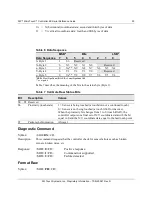
Xx = X (horizontal) coordinate data; second and third bytes of data
Yy = Y (vertical) coordinate data; fourth and fifth bytes of data.
Table 6 Data Sequence
MSB*
Bits
LSB*
Data Sequence 7
6
5
4
3
2
1
0
S- Byte 1
1
S6
Reserved
X- Byte 2
0
X3
X2
X1
X0
Reserved
x- Byte 3
0
Xs** X9
X8
X7
X6
X5
X4
Y- Byte 4
0
Y3
Y2
Y1
Y0
Reserved
y- Byte 5
0
Ys** Y9
Y8
Y7
Y6
Y5
Y4
*MSB = Most Significant Bit, LSB = Least Significant Bit
** s = sign bit
Table 7 describes the meaning of the bits in the status byte (Byte 1).
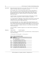
Table 7 Calibrate Raw Status Bits
Bit
Description
Values
S0 – S5 Reserved
—
S6
Proximity (touch state)
1 = Sensor is being touched (a touchdown or a continued touch).
0 = Sensor is not being touched (a touch liftoff or inactive).
When the proximity bit changes from 1 to 0 (touch liftoff), the
controller outputs one final set of X/Y coordinate data with the bit
equal to 0 and the X/Y coordinate data equal to the last touch point.
S7
Packet synchronization
Always 1.
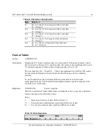
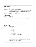
Diagnostic Command
Syntax:
<SOH>DX<CR>
Description:
This command requests that the controller check for sensor failures such as broken
corners, broken wires, etc.
Response:
<SOH>0<CR>
Positive response.
<SOH>1<CR>
Command not supported.
<SOH>2<CR>
Failure detected.
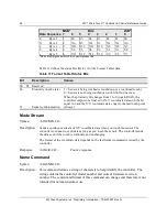
Format Raw
Syntax:
<SOH>FR<CR>
Summary of Contents for MicroTouch EX Series
Page 8: ......


