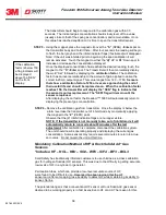
38
087-0020 REV
E
A Fail indication is usually a result of either a removed or poor sensor-to-housing
electrical connection or sensor failure discovered by the self-diagnostic routine. The self-
diagnostic routine interrogates transmitter and sensor memory transfer integrity and is
continuously performed by the Series 5000 transmitter. Should a failure occur,
transmitter mA output goes to 3.1mA.
Sensor Strength Failure Indication – “SEN”
This flag will only appear after a system calibration, when the transmitter has calculated
a calibration factor of less than 150. This helps indicate to the operator that the sensor
requires replacement. The “SEN” flag will remain on until sensor is replaced. There is no
effect on the transmitter’s mA output.
Sensor Self-Test – “SST”
This flag will
flash
if the Sensor Self-Test operation failed or if the unit was unable to
enter the SST mode because the transmitter was reading a full scale indication of 5% or
higher.
Series 5000 Fault Codes
“F01” Indication (Loop Calibration Failure) – Calibration created an unacceptable output
“F02” Indication (Failed SST Operation) – Sensor self-test failed
“F04” Indication (Reserved For A Future Fault)
“F08” Indication(Missing Sensor Indicator) – Missing sensor or poor connection of
sensor to sensor housing, e.g. bad or wet elastomeric pad.
Sensor Self Test (SST) Option
The Sensor Self Test (SST) option provides a means for automatically testing the
electrochemical gas sensor. This is equivalent to the traditional bump testing of a
sensor. Test gas is generated by applying a low level voltage to a cell containing
electrolyte. This cell is called a generating cell. The voltage causes the electrolyte to
create a small quantity of gas that diffuses up into the electrochemical sensor. This
diffusion will operate in wind speeds up to 23 MPH. The generating cell is capable of
generating more than 760 tests allowing a test to be run once a day for two years.
Although not a calibration test, it does automatically indicate when the sensor is no
longer able to respond to a gas leak. This powerful feature provides additional
confidence in your gas detection system. Contact your local Scott Safety representative
to ascertain which sensors can be fitted with this option. The controls for starting and
stopping the Self Test function are accessed through the front display by touching either
the
UP or
Down spot twice with a magnet. (This mode can only be accessed if the
CPU board has been fitted with the SST components.)
After touching the
UP or
Down spot “
Ihb
” will be displayed. Touch the same spot
again and
“SSt”
will be displayed. Touch the
’’S’’
(SPAN) -
Enter
spot and the
following will appear:
Freedom 5000 Universal Analog Toxic Gas Detector
Instruction Manual


