Kit Instructions
• Lane Pay Station E-Switch Kit Instructions
8
Lane Pay Station E-Switch Kit Instructions - Version 1
75-0302-1496-1
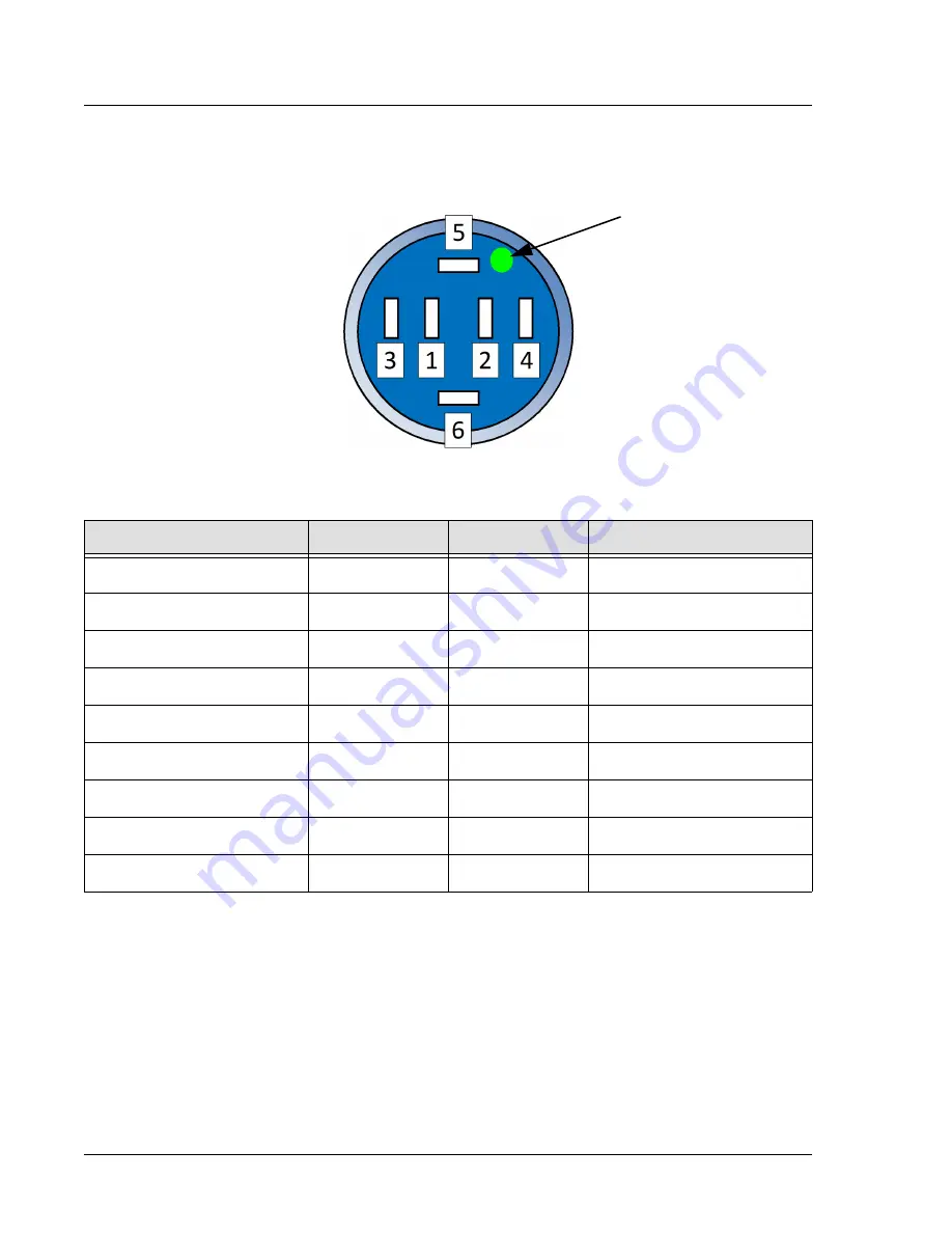
Figure 1.6
E-Switch Button Pin Numbering
7.
Complete the PC Board connections (Figure 1.7 on page 9).
a.
Move the BUTTONS connector from Recp 14 to J3 (positions 4 - 7).
b.
Move the SECURITY connector from Recp 13 to J3 (positions 8 - 12).
Table 1.1
Wiring Table
From
Wire Color
Cable
To
Lost Button, Pin 3
White
I/O
I/O Board, J3.4
Receipt Button, Pin 3
Green
I/O
I/O Board, J3.6
Cancel Button, Pin 3
Red
I/O
I/O Board, J3.7
All Buttons, Pin 4
Black
I/O
I/O Board, J3.5
All Buttons, Pin 1
Black
Power
Power Supply, Pin 7
All Buttons, Pin 6
Red
Power
Power Supply, Pin 2
Lost button, Pin 2
Red
Jumper
Lost Button, Pin 5
Receipt Button, Pin 2
Red
Jumper
Receipt Button, Pin 5
Cancel Button, Pin 2
Red
Jumper
Cancel Button, Pin 5
Ring color dot


