

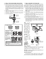

G. INSTALL THE FEED WATER CONNECTION AND TUBING
1) Open faucet and turn off cold water feed valve to relieve pressure.
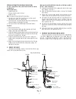
2) Locate the cold water stem on the underside of the faucet fixture.
Unscrew the cold water feed tube from the faucet stem. Locate the
Faucet Adapter that came with your drinking water system. Insert
the black gasket into the threaded adapter and tighten onto the
Faucet Cold Water Stem under the sink, making sure that 1/4” side
connection is accessible and not facing the wall. Make sure not to
overtighten.
3) Take the Cold Water Feed Tube and attach to the Faucet Adapter,
making sure not to over tighten.
4) Locate the 1/4” Orange Tubing and insert into the 1/4” outlet of
Faucet Adapter. See Figure 3 and “Using Push-in Fittings” below.
5) Leave cold water supply off.
H. PREFILL AND SANITIZE THE STORAGE TANK
Prefilling the storage tank is always recommended so that there is
pressure to check for leaks as well as sufficient water to flush the carbon
block post-filter. It is important to use a sanitizer when prefilling the tank
so the solution can sanitize the tubing, fittings, and the faucet at start up.
1)
Remove protective cover from storage tank and discard. Pour a half
teaspoon of common unscented household bleach (5.25%) into the
end of the tank. Apply PTFE tape (not included) to threaded tank
connection and install tank valve onto connection.
Do not over
tighten.
Open the tank valve so that the tank valve handle is parallel
to the valve body.
2)
Connect one end of the 3/8” yellow tubing into quick connect
tank valve. Connect the other end of the 3/8” yellow tubing to the
included 3/8” x 1/4” union connector.
3)
Connect the free end of the 1/4” orange feedwater tubing to the other
end of the 3/8” x 1/4” union connector.
4)
Open the cold water feed valve (making sure the tank valve is still
open) and allow the tank to fill (about 3 minutes).
5)
Close the cold water feed valve and the tank valve. Disconnect the
orange and yellow tube from the union connector, setting the tank aside
while proceeding with the rest of the installation (the sanitizing solution
should be kept in the tank for at least 15 minutes). Refer to the “Using
Push-In Fittings” section.
NOTE:
If you
encounter difficulty in
removing the tubing
from the 3/8” x 1/4”
union connector,
make sure the tank
valve is closed and
cut the yellow tubing
approximately 1”
away from the
tank valve fitting to
relieve the pressure.
Remove the 1” piece
from the tank fitting.
IMPORTANT:
After
the installation
is complete, it is
recommended that
the 3/8” x 1/4” union
connector be saved
for future use in tank
sanitization.
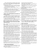
I. INSTALL
THE DRAIN
CONNECTION
IMPORTANT:
Before starting this
procedure, inspect the
condition of the drain piping, especially in older homes where the traps
and tailpieces can be deceptively thin and frail. If they are in poor
condition, replace prior to installing the drain connection.
IMPORTANT: Some local plumbing codes may prohibit the use of
saddle-type drain connections.
Undercounter Installation:
The drain saddle assembly is designed to fit around a standard
1-1/2” OD drain pipe. For smaller (lavatory type) or larger (ABS pipe)
drains, consult your professional installer for special drain saddles.
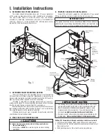
MOUNT
HERE
NEVER
MOUNT
HERE
GARBAGE
DISPOSAL
Fig. 4
7
Vertical Position
Horizontal Position
Nut
Screw
Drain Saddle
Elbow
IMPORTANT:
Hole should be located on
top of the pipe if drain saddle
is positioned horizontally.
Drain Saddle
Halves
Fig. 5
Fig. 3
1/4” Orange
Tubing
Faucet Stem
Undersink
Faucet Adapter
Cold Water
Feed Tube
Collet
Backstop
“Using Push-In Fittings”
CAUTION
To Attach Tubing
Push tubing in as far as
it will go. Tubing must
be inserted past o-ring
and hit backstop. Pull
tube to ensure it is
secured.
To Release Tubing
Push in grey collet to
release tubing. With
collet held, pull tubing
straight out.
To reduce the risk associated with property damage due to
water leakage:
•
Ensure all tubing and fi ttings are secure and free of leaks.
Correct
Incorrect
Cut Tubing Straight


