background image

3D Systems, Inc.

6

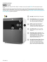
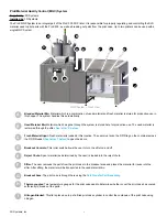
Blended Material Bin: 

Material which is a combination of used material and fresh material is stored for production use in 

this hopper . The system handles this automatically .

Used Material Bin: 

Material which has gone through the system is stored here for production use . The used material is 

reclaimed through the sifter . 

See letter ‘F’ below

.

Fresh Material Input: 

Fresh material is loaded at this location . The user must scan the RFID tag on the container across 

the RFID Reader 

(See letter ‘I’ below)

 to open the doors .

Breakout Controls: 

This roller switch allows the user to turn the sifter on and off .

Reject Chute: 

Spent material (as determined by the user) is loaded into the reject chute .

Sifter:

 The user removes the parts from the print cake in the breakout area and places the material for reuse into the 

sifter . After sifting, the material will be transported to the used material bin .

Breakout Area:

 The print cake is brought here using the 

Part Transfer Cart Assembly

 .

Thermocouples:

 Two temperature gauges for the print cake used to determine whether or not the print cake has cooled 

sufficiently to break out the parts.

Nitrogen Blanket:

 This lid is placed on top of a filled print cake cylinder to control the cooldown of the print cake using 

nitrogen .

A

B

C

D

E

F

G

H

I

J

I

G

H

F

E

D

C

K

L

MQC System – Front View

ProX Material Quality Control (MQC) System

Supplied by

: 3D Systems

Installed by

: 3D Systems

The ProX MQC System is an integral part of the ProX 500 3D Printer . It is responsible for properly regulating and controlling the SLS 

material used to print parts with the ProX 500, as well as breaking out parts from the print cake . Up to two printers can be used with a 

single MQC System .

B

A

Summary of Contents for ProX 500

Page 1: ...ProX 500 3D Production Printer Facility Guide Original Instructions...

Page 2: ...0 SLS 3D Printer and Auxiliary Equipment 15 ROOM REQUIREMENTS 16 Clearance Requirements ProX 500 Station 16 Clearance Requirements ProX MQC System 16 Floor Requirements 16 ATMOSPHERE REQUIREMENTS 17 E...

Page 3: ...e system 26 Moving Safety Guidelines 27 Moving the ProX 500 SLS Printer Station and MQC System 28 ProX 500 Printer and MQC System Placement 29 Installation Verifications performed by 3D Systems 29 Sto...

Page 4: ...ts for the ProX 500 SLS 3D Printer ProX Material Quality Control System and auxiliary equipment SAFETY PRECAUTIONS Please review all safety information in the Safety Guidelines and Instructions sectio...

Page 5: ...are indicated in each section The facilities for these non 3D Systems supplied components and in some cases the components themselves must be in place before the ProX 500 MQC System and any auxiliary...

Page 6: ...rea There are two doors in front of the Print Chamber the outer locking door and the inner print chamber door The parts are printed inside the Print Chamber E Stop The Emergency Stop button is a safet...

Page 7: ...in the breakout area and places the material for reuse into the sifter After sifting the material will be transported to the used material bin Breakout Area The print cake is brought here using the Pa...

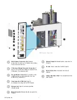
Page 8: ...FID Reader The RFID reader is used to scan the RFID tag of the material container This ensures that the system keeps track of material quantity and fresh to new powder ratios The tag must be scanned t...

Page 9: ...connected here If not the connection is jumpered out Compressed Air CDA Inlet Input for compressed air coming into the MQC System Nitrogen Inlet Input for customer provided nitrogen supply Material O...

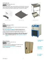
Page 10: ...Systems comes to install the system See Chiller Coolant Requirements on page 20 Nitrogen Generator Supplied by 3D Systems P N 104011 02 Installed by 3D Systems 3D Systems manufactures a High Performan...

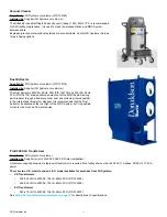
Page 11: ...or customer P N 134105 Installed by Supplier 3D Systems or customer The Dust Extractor 230VAC 60Hz 3PH P N 134105 and 400VAC 50Hz 3PH P N 134105 draws airborne powder out of the MQC System during par...

Page 12: ...all of your ProX 500 room Refer to the safety guidelines included in the ProX 500 User Guide for information on safely working with nitrogen and oxygen Bead Blaster Supplied by 3D Systems P N 26106 10...

Page 13: ...iquid to gas volume conversion ratio so you can properly size your tanks SLS Materials The material listed below is available for purchase from 3D Systems The material comes with its own 3D Systems Ma...

Page 14: ...l your ProX 500 SLS System To keep delays and costs to a minimum verify that you have sufficient quantities of distilled water and OptiShield on hand before installation Caution Use only distilled wat...

Page 15: ...er Facility Requirements Poster on page 33 for example when you lay out the room or wire electrical power The instructions tell you when you need to refer to this drawing After your facility meets all...

Page 16: ...llation Contact name Phone email fax Phone Email Fax Facility address Date submitted Room Requirements completed Atmosphere Requirements completed Electrical Requirements completed Measured facility p...

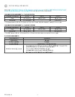
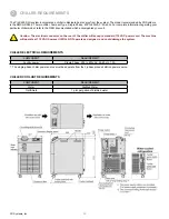
Page 17: ...IREMENTS ProX MQC SYSTEM MINIMUM CLEARANCE WIDTH DEPTH HEIGHT Room 481 cm 16 ft 427 cm 14 ft 305 cm 10 ft Access door1 290 cm 9 5 ft 260 cm 8 5 ft 1 The MQC System is 244 cm 8 ft tall and 275 cm 9 ft...

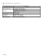
Page 18: ...ng and air conditioning installed A C not blowing on top of process station Temperature Operating range 16 to 27 C 60 to 80 F Setpoint range 18 to 24 C 65 to 75 F Stability 2 C 5 F Non condensing rela...

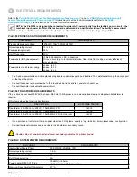
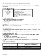
Page 19: ...directly from the facility s power circuit to the machine s input power line filter This task must be performed by a qualified electrician The facility s power circuit must have a 50A branch protectiv...

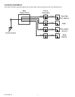
Page 20: ...EMENTS All connections between powered equipment and the power panel must be grounded as shown in the diagram below 5 5 5 5 5 5 5 5 ProX 500 SLS System MQC Non Igniton Vacuum Bead Blaster Main Power P...

Page 21: ...ed your unit Caution The electrical connector on the rear of the chiller will accept a standard 110 VAC power cord The machine will operate at 110 VAC however it WILL NOT operate as designed and could...

Page 22: ...gen from ambient air CDA required creating two air streams N2 supply and O2 waste Both exit at the bottom of the generator The N2 supply stream is greater than 99 nitrogen The O2 waste stream is less...

Page 23: ...r material handling peripheral equipment for part finishing and items consumed during part prints such as nitrogen material and filters Required and Optional System Components REQUIRED ProX 500 SLS PR...

Page 24: ...xample below include the equipment plus the pallet or crate Shipping configurations may vary from this example NOTE For bare equipment weights and dimensions without pallets and crates included see Sy...

Page 25: ...ditive for chiller coolant pint 1 132561 00 Chiller Plumbing Kit 3 2580 03533 Fitting Push lock Parker G0182 8 8B 2 2580 03534 Fitting Street Elbow Parker L2202P 8 8 24 2580 03535 1 2 Hose Parker 7212...

Page 26: ...2 cm 88 lb 15 in 20 in 24 in Transformer Step Down 240 208 VAC 3 phase 60 Hz 10 kVA 127 kg 56 cm 23 cm 41 cm 280 lb 22 in 9 in 16 in Transformer Step Down 385 415 208V 3 phase 50 Hz 10 kVA CE approved...

Page 27: ...SLS system is designed to be lifted and moved with a pallet jack or forklift Do not try to lift or move it manually Have an assistant help you if you choose to remove the Nitrogen Generator or SLS sys...

Page 28: ...should be at least 48 4ft 1 2m long When moving crated equipment only lift crates with forks parallel to crate skids and fully inserted in channels between skids When moving uncrated equipment insert...

Page 29: ...t from the front or back following the fork guides at the bottom of the frame When moving the MQC System observe the following Forks used to move the MQC System must be at least 66 5 5ft 1 7 m long Th...

Page 30: ...ce your 3D Systems Field Service Representative will make the required nitrogen power and coolant hook ups and connections The representative will also level the process station then perform the follo...

Page 31: ...ystem that is connected to the MQC and another that is connected to the facility s LAN To share the resources of the MQC System up to two printers can be connected to each MQC System The ethernet conn...

Page 32: ...email moreinfo 3dsystems com www 3dsystems com NYSE DDD Customer Support Hotline USA 1 800 793 3669 Asia Pacific 852 29 23 50 77 Europe 49 6151 357 0 Sales and Service Phone Numbers France 49 6151 357...

Page 33: ...3D Systems Inc 32 ProX MQC MATERIAL QUALITY CONTROL SYSTEM FACILITY POSTER 12 94 7 in 2405 mm 54 5 in 1384 mm FRONT TOP CEILING Rear Access Panels...

Page 34: ...F and 75 F temperature should be constant to 2 C 5 F Chiller power panel single phase separate from process station power Process station power panel Input 208VAC 50 60Hz 3PH 10kVA separate from chil...

Page 35: ...3D Systems Inc 333 Three D Systems Circle Rock Hill SC 29730 www 3dsystems com 2015 3D Systems Inc All rights reserved pn 134011 00 Rev C...

Reviews: