page
22
... print your plane | www.
3DLabPrint
.com
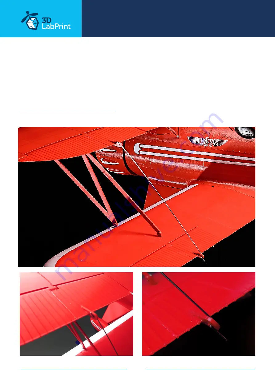
7.4 Aileron mounting
Glue the horns on ailerons and use a piano wire with Z bends as push rods.
you will need:
1,2mm steel wire
See video guide Wings final assembly
Page 1: ...page 1 print your plane www 3DLabPrint com Fully 3d printable WACO YMF 5 scale 1 6 5 wingspan 1442 mm 56 8 inch User Guide rev 2021 08 ...
Page 2: ... just for a cost of filament Extensive hi tech 3d structural reinforcement making the model very rigid while maintaining a lightweight airframe and exact airfoil even it s just a plastic This perfect and exact 3d structure is possible only thanks to additive 3dprinting technology So welcome to the 21st century of model flying and be the first at your airfield Easy to assembly you don t need any ex...
Page 3: ...po 3230 g 113 9 oz Max takeoff weight 3500 g 123 46 oz Never exceed speed VNE 100 km h 49 mph Design maneuvering speed VA 60 km h 31 mph Stall speed VS 25 km h 9 4 mph Recommended setup Motor Turnigy SK3 5055 430KV for 6S setup or any 5055 430 380grams motor for 6s setup ESC 80A 6s with UBEC or any 6s 60 100A connector suitable for battery Battery 2700 3300 mAh 6S or any 6s 500 600g Propeller wood...
Page 4: ...ots for sporting and other uses and continued in production through the late 1930s The 1934 model YMF was substantially redesigned with a longer and wider fuselage larger rudder and other structural changes and put into production in March 1986 by WACO Classic Aircraft of Lansing Michigan as the YMF 5 Over 150 YMF 5s were completed as of 2017 with new examples being built to specific orders Consid...
Page 5: ...re using PRUSA i3 ORIGINAL printers so you may need to adjust the basic printing parameters to match your printer or use these files as a start point for you Please check the Simplify3D 3 Step By Step PDF VIDEO userguides Apart from this userguide please see the Printing Guide to find some Tips and Advice for airplane printing Thin Wall Printing 4 Gcodes Basic Gcodes prepared for direct use as uni...
Page 6: ...like Simplify3D there is always option to use another free slicer Please follow our Cura guide in the Help section of the website where you can find the basic single wall profile 6 Scale markings PDF You can cut the decals from a self adhesive vinyl foil create stencils or use any other favorite method of decorating the model ...
Page 7: ...page 7 print your plane www 3DLabPrint com Lenght 1094 mm 43 1 inch Wing area 54 5 dm2 7 0 square foot WACO YMF 5 Centre of Gravity Centre of Gravity 120 mm 120 mm ...
Page 8: ...page 8 print your plane www 3DLabPrint com Wing span 1442 mm 56 8 inch ...
Page 9: ...nt com 2 Create account download You will receive download link to all the zipped files to your email please check your spam folder if not or you can log in to your account and download directly from our websites 3 Gcodes preparing option A Gcodes if your printer is i3 comptatible you can use prepared gcodes directly Just save them to the SD card and let the 3d printer do it s job HE temperature i...
Page 10: ...t single parts and so on Most 3d printers should work just with these settings but please go through the settings and amend if necessary we are not liable for any damage resulting from using our settings If this still does not work for you please proceed to the next option option C Simplify3D manual setting watch and learn Use our Simplify3D reference guide for proper setting this is very good opt...
Page 11: ... Please visualise our presliced gcodes to see how the result should look like and try to achieve the same in your slicer Please try to find the best extrusion multiplier and temperature for good weight and best possible layer bonding Consult the parts weight list for proper multiplier settings As a starting point you can use our predefined CURA profile available in the Help section on the website ...
Page 12: ... Prepare your printer and start printing we prefer to use SD card rather than direct USB connection Scaling the model will lead to unusable result you will need Polyair 1 0 or any PLA filament 3DLac Strong hair spray PEI or your favorite adhesive bed surface Razor blade Please see the Help section at 3dlabprint com ...
Page 13: ... R4 13 g 0 46 oz aileron upper L1 13 g 0 46 oz aileron upper L2 15 g 0 53 oz aileron bottom L1 7 g 0 25 oz aileron bottom L2 7 g 0 25 oz aileron bottom L3 15 g 0 53 oz aileron upper R1 13 g 0 46 oz aileron upper R2 15 g 0 53 oz aileron bottom R1 7 g 0 25 oz aileron bottom R2 7 g 0 25 oz aileron bottom R3 15 g 0 53 oz wing struts pair 40 g 1 41 oz wing pin 3 g 0 11 oz tail horizontal stabiliser L1 ...
Page 14: ...ht position Glue the pins after you check the proper alignment See video guide Wing Assembly you will need CA Glue medium viscosity activator 1 2 1 5 mm carbon fiberglass or steel wire for aileron hinge 2pcs of 10 mm carbon tube 780 mm upper wing 2pcs of 10 mm carbon tube 610 mm bottom wing 3x M3 nut 3x M3x20 screw 2mm self screw Snap knife Some cloth for wiping CA glue wing bottom 1 72g 2 54oz fu...
Page 15: ...cowling onto cylinders and glue the assembly The scale engine replica is fitted with M4x20 bolts and nuts Fit the optional scale accessories such as seat headrest instrument panel windshield pilot See video guide Fuselage Assembly you will need CA Glue medium viscosity activator Snap knife or Sandpaper 1x ball pen spring F1 124g 4 37oz motor mount 25g 0 88oz engine case 75g 2 65oz engine valves 80...
Page 16: ... wire Glue elevator lock to the fuselage Mount the rudder assembly to the vertical stabilizer using the 1 2 1 5 mm carbon rod or steel wire Elevator and rudder should move freely controlled by the pushrod and servo Check the functionality of the elevator and rudder assembly you will need CA Glue medium viscosity activator 1 1 2 mm steel wire for elevator and rudder pushrod 1 2 1 5 mm carbon or ste...
Page 17: ...ds into the fuselage Secure the carbon rods with screws fit and assemble the holders Assemble the wheels discs and tyres and secure them inside boots using M3x30 bolts You can add a scale wire spring system but it s not necessary for correct function you will need CA Glue medium viscosity activator 4 mm carbon rod 2pc 316 mm 2pcs 270 mm 2x M3x30mm screws 6x 3x20mm self tapping screws 4x M3 nuts op...
Page 18: ...desired shape Secure the wheel using a collar Insert the assembly into the hole in the rudder Bend the wire to the rear and make sure the wheel is aligned with the rudder Glue the wire into the rudder well you will need 1 5 2 mm piano steel wire 150mm Pliers Any small wheel See video guide Landing Gear 2 tail skid 1 5 mm steel wire tail wheel disc 1g 0 04oz tail wheel tyre 4g 0 14oz FLEX the hole ...
Page 19: ...ervos and aileron control horns Elevator and rudder servo will be fixed directly to the fuselage by included screws See video guide Servos installing 1 See video guide Servos installing 2 you will need 4x Hitec HS 82MG or Corona CS 238MG or any similar sized servos 30x12x30mm 1 17 x 0 47 x 1 16 inches 2x servo extension cables 300mm 12 inch Snap knife Z pliers 1 2 mm steel wire ...
Page 20: ...ler Simply glue it from back side Glue universal motor mount with motor into the fuselage in right position Fix the battery 400g pack needed by velcro tape and mount it in the front of the fuselage find the perfect balance and CG position by moving it See video guide Motor Mount you will need CA Glue medium viscosity activator 4x M3 screws and nuts 7x self tapping screws 3 5 15mm motor mount 25g 0...
Page 21: ...Make sure the bolts and nuts are aligned properly before glueing for good Repeat the same for the upper wing Left and right wing struts are symetrical and marked by L nad R letters Fuselage struts are marked by L and R letters Letter must be visible in front and up after fuselage montage Push completed struts with pins to the fuselage and wings Double check the wing and fuselage position and glue ...
Page 22: ...ge 22 print your plane www 3DLabPrint com 7 4 Aileron mounting Glue the horns on ailerons and use a piano wire with Z bends as push rods you will need 1 2mm steel wire See video guide Wings final assembly ...
Page 23: ...ur favourite marking You can use our scale PDF for make painting mask and easy paint job Refer to your R C system userguide for setup information Install your reciever connect battery setup servos and etc with your trasmitter check servo position then install propeller Make sure the battery is positioned properly and secured with wing battery holder if battery moves during flight it can shift the ...
Page 24: ...decrease elevator and ailerons deflection to calm down the plane Make sure the battery is well fixed in proper possition If it moves during flight it will cause shifting of CoG aft and will result in uncontrolable flight behavior After gaining some confidence you can balance the plane to the Center of Gravity marks and set Expos to 60 as shown in the video instructions this gains back extra maneuv...
Page 25: ...tery 2700 3700mAh 6s weight around 400 600g Servos 4x Hitec HS 82MG or Corona CS 238MG 30x12x30mm 1 17 x 0 47 x 1 16 inches Glue fresh CA Glue medium viscosity activator Other 2x servo extension cables 300mm 12 inch 2pcs of 10 mm carbon tube 780 mm upper wing 2pcs of 10 mm carbon tube 610 mm bottom wing 2pcs of 4mm carbon rod 316 mm 2pcs of 4mm carbon rod 270 mm 3x 1m of 1 1 2 mm 14 AWG pushrod wi...