3D Joy JoysMaker R2 Assembly Manual Download Page 35

JoysMaker

  3DJoy  version  R2  assembly  guide                               


1.5   

Install the Z Printing platform 

1.5.1   

Preparation 


Time needed


20~40 minutes. 


                                                                  Item list 

Items 

Qty. 

Description 

Z Printing platform 


12mm Z Rods 


M8 Threaded rod


Oil 


1.5.2   

Install the printing platform 

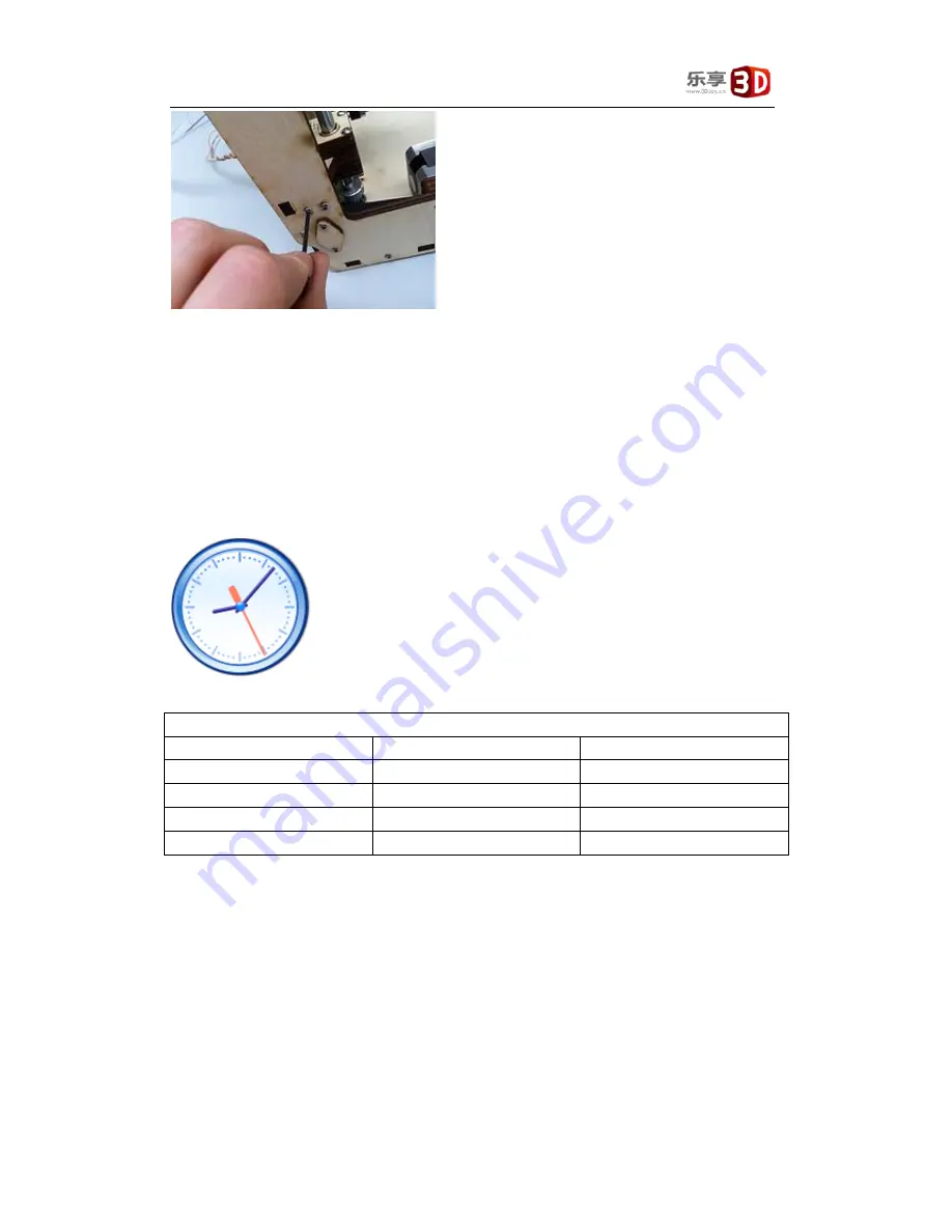
1.  Put the Z platform into the machine, and insert 12mm rods from the top panel holes 

into the machine and cross the Z printing platform and finally fit into the hole on the 

bottom platform, as bellow: 

Summary of Contents for JoysMaker R2

Page 1: ...JoysMaker R2 Assembly Guide use it combine with machine user guide Version Date Main Content 2014 05 12 Initial version ...

Page 2: ... 3 3 Step2 install the bear cap and slice blocks 2 1 3 4 Step3 install the axis and slider 3 1 4 Install the printing head 1 1 4 1 Preparation Work 1 1 4 2 Install the printing head 1 1 5 Install the Z Printing platform 8 1 5 1 Preparation 8 1 5 2 Install the printing platform 8 1 5 3 Smear lubricant oil 15 1 6 Install the extruder 16 1 6 1 Preparation 16 1 6 2 Assemble 16 1 7 Assemble the LCD and...

Page 3: ...mble the power outlet 25 1 11 4 PCB connections 26 1 11 5 Connect the wires 27 1 12 Assemble the relay and cabling to the heated build platform 29 1 12 1 Preparation 29 1 12 2 Components 29 1 12 3 Assemble the Relay with attached cables 29 1 13 Leveling the printing platform 33 ...

Page 4: ...contract encapsulation assembly printers below in the assembly process indicating the name of this step needed components 1 0 2 Some Conception Metric the product is most used in the design of the metric system mm and m Use another dimension is inch inches and inches Most of the parts are using the M3 3 mm diameter T Slots and tabs Note some may show on the drawing is not the T slot but is the squ...

Page 5: ...1 1 1 Assembly good framework for rendering As above such as frame part is not smooth can use sand paper burnish but don t be too hard to prevent the fracture 1 1 2 Preparation Time Needed General need 20 to 30 minutes Tools Needed 2mm Hexagon screwdriver ...

Page 6: ... Together usage with M3 screw Hang machine block slice 11A 1 Used on back frame to hang the feeder Z axis blocks pieces 3A 2 Z axis blocks Velcro 4 Limit switch wires connect to the frame 1 1 3 Step1 install Limited Switch The required items list Items Qty Description FRONE Panel 1 Marked with FRONT BACK Panel 1 Marked with BACK LEFT Panel 1 Marked with LEFT Limited Switch 6 5long 1short 10mm M3 s...

Page 7: ...置应和面板标识字 FRONT BACK LEFT 同侧 限位开关的弹簧片应朝向内侧 为方便后续安装 各面板上限位开关编号如图 后续限位开关描述均按照此编号 Note Short wire limit switch located at the bottom of the BACK panel Limit switches shall be installed at the mark on the panel The location of the limit switch should be on the same side with the panel logo word FRONT BACK LEFT The spring leaf should be toward the inside of limit switch In order to facilitate subsequent...

Page 8: ...ation Left panel installation Back panel installation Limited switch downward use the ones with short wires In order to facilitate subsequent adjustment for the limit switch can be mounted with 2 thin spacers Back panel installation Back panel installation NOTE Washers behind screw heads Till now the limited switches are assembled ...

Page 9: ... Nylon bands 4 1 Put the back panel on the table marks face up 2 Insert the TOP panel by placing the tabs of the top panel into the slots of the back panel 3 Do the same with the BOTTOM panel and then place the FRONT panel on both 4 Now fit the RIGHT side panel fix with a few bolts then the LEFT panel 5 Use the tie bind the limited switch wires to the corner for the frame ...

Page 10: ...JoysMaker 3DJoy version R2 assembly guide 10 6 Install all the screws and then you will have this part of work finished ...

Page 11: ...rame Item list Item Qty Description 11A 1 3A 4 16mm M3 Screws 8 M3 Nuts 8 1 11A install the screws from the outside of the machine or else you the screw may scratch with the printing bed 2 Install the TOP panel and the BOTTOM PANEL with blocks like 3A as bellow Till now the part is finished ...

Page 12: ...ist Item Qty Description Motor 3 2 with long wires 1 with short wire 10mm M3 screw 4 Z Motor 20mm M3 screw 8 X Y Motors Short Pulley belts 2 X Y Motors 5mm Pulley 2 X Y Motors coupling 1 Z Motor Nylon column without threads 8 X Y Motors 1 2 2 X Y Motor Pulley assemble Item List Item Qty Description Motor 2 X Y Motor Pulley 2 As bellow pulley on X Y motor screw tightly ...

Page 13: ...m List Item Qty Description 20mm M3 Screws 8 Nylon column without threads 8 Motor 2 With Pulley Short Pulley belt 2 1 Insert screw into the frame panel from front side put the Nylon column onto the screw 2 Put the short belt onto the pulley 3 Screw the motor onto the frame ...

Page 14: ...scription Motor 1 Short wire Coupling 1 10mm M3 Screws 4 1 Put the short wire motor under the bottom Panel note Motor line towards the inside of the Bottom panel 2 10mm M3 screws to install the motor onto the frame 3 Put the coupling onto the motor axis and screw it tightly onto the motor ...

Page 15: ...rew driver Item List Item Qty Description 8mm ball bearing 8 10mm M3 Screws 16 16mm M3 Screws 16 30mm M3 Screws 16 M3 Nuts Some 8mm short rod 2 X axis 8mm long rod 2 Y axis Long pulley belt 4 Pulley 8 Bearing block no holes 8 Assembled on the outside Bearing cap with holes 6 Assembled on the inside 1 3 2 Step1 install the ball bearing Put 8 ball bearings into the frame as bellow ...

Page 16: ...ty Description Bear cap 6 With holes Bear block 8 Without holes M3 Nuts 16 16 mm M3 Bolts 16 1 Bear caps and bear blocks holds the bears from outside and inside prevent printer bearing fall off during operation shown as the figure Blue for the bear caps red for bear blocks pay attention to the number of screws ...

Page 17: ...Item list Item Qty Description 8mm short rods 2 8mm long rods 2 Pullley 8 Belts 4 Sliders 4 With FRONT BACK LEFT RIGHT engraved 1 Start with the rods assembles work 2 Check whether the length is correct 2 long ones and 2 short ones Short ones are used from the left to right panel and the long ones are these from the front to back panels Let s start with the short one ...

Page 18: ...y 6 Put the slider engraved with FRONT onto the rod with the characters facing towards the LEFT i e the slider raised portion shall be able to hit the limit switches 7 Put the other pulley onto the rod 8 Put the other belt onto the pulley and insert the rod into the bear block and then the bears embedded in the panels 9 Screw tight the bear caps with bolts ...

Page 19: ...JoysMaker 3DJoy version R2 assembly guide 5 ...

Page 20: ... onto the rod pay attention to direction of the pulley refer to bellow photo 13 Put onto the pulley the belt which is already installed in the previous step 14 Put on the slider with BACK engraved characters facing the RIGHT of the machine 15 Put on the other pulley and the other already installed belt ...

Page 21: ...ysMaker 3DJoy version R2 assembly guide 7 16 Put on the 3rd pully for motor pay attention to the direction 17 Put on the short belt 18 Insert the rod into the hole of the bear 19 Screw tight the bear cap ...

Page 22: ...anel 21 Put on one pulley 22 Put one long belt onto the pulley 23 Put on the slider engraved with LEFT the characters facing the front side of the machine 24 Put the 2nd pulley onto the rod 25 Put on the other long belt onto the 2nd pulley 26 Insert the rod into the hole of bear embedded on the panel ...

Page 23: ...ght rod 28 Insert from the right side of the back panel with a log rod 29 Put on one pulley 30 Put the long belt previously installed on the left rod onto the pulley 31 Insert the slider engraved with RIGHT characters facing the BACK panel 32 Put on the 2rd pulley onto the rod ...

Page 24: ...Joy version R2 assembly guide 10 33 Put the other long belt installed previously onto the pulley 34 Put on the 3rd pulley for motor 35 Put the short belt onto the pulley 36 Insert the rod into the hole of the bear ...

Page 25: ...JoysMaker 3DJoy version R2 assembly guide 11 ...

Page 26: ...r 3DJoy version R2 assembly guide 12 37 Belts need to be clipped onto the slider Start with the Front slider Shown as bellow 38 Similar for the back one 39 Let and right sliders are a bit more complex as bellow ...

Page 27: ...JoysMaker 3DJoy version R2 assembly guide 13 40 Now we have 4 small pieces engraved with C Will be used later Till now the X Y Rod and sliders are installed ...

Page 28: ...n Work Time needed 60 90 Minutes Tools needed 2mm screw driver 1 4 2 Install the printing head Item list Item Qty Description Printing head 1 Bowden tube 1 6mm rod 2 Inserted into the printing head Part engraved with C 4 Fasten the belt on the slider 30mm M3 bolts 4 12mm M3 bolts 4 M3 Nuts 8 ...

Page 29: ...assembly guide 2 1 Insert Bowden tube into print head 2 Put a part C onto the slider but don t screw it tight at the moment 3 With a 6mm axis insert it across the printing head pay attention to the direction of the printing head ...

Page 30: ...DJoy version R2 assembly guide 3 4 Insert the other 6mm axis from the front to the back into the printing head 5 Gently insert the 6mm axis into the sider 6 Insert the other side of the axis into the other slider ...

Page 31: ...JoysMaker 3DJoy version R2 assembly guide 4 6 Screw tight the belts and the axis with the C parts 7 Finally screw the 30mm bolts onto the sliders 8 Now screw tight all the other bolts on the sliders ...

Page 32: ... is installed but you need to make sure the axis is parallel with the frame i e orthogonally crossed 10 Loosen the include bolts on all the 8 pulleys Then adjust the sliders and axis until the XY axis is orthogonally crossed Then screw tight the include bolts again ...

Page 33: ...JoysMaker 3DJoy version R2 assembly guide 6 ...

Page 34: ...ion of the limited switches of the X direction and Y direction When move the printing head to the both ends of the X direction you should be able to hear click sound which is made by the limited switches That means the slider can trigger the closer of the limited switch If you can t hear this that means you will have to adjust the position of the limited switch or the sider 13 Repeat step 12 for t...

Page 35: ...Item list Items Qty Description Z Printing platform 1 12mm Z Rods 2 M8 Threaded rod 1 Oil 1 1 5 2 Install the printing platform 1 Put the Z platform into the machine and insert 12mm rods from the top panel holes into the machine and cross the Z printing platform and finally fit into the hole on the bottom platform as bellow ...

Page 36: ...JoysMaker 3DJoy version R2 assembly guide 9 Screw the 3B blocks on the top panel to cover the holes ...

Page 37: ...M8 threaded rods into the machine from the top panel and screw into the Z big copper nut till reaching the coupling Sometimes you will receive threaded motors which will integrated the motor and the threaded rod Screw tight the threaded rod and the coupling ...

Page 38: ...JoysMaker 3DJoy version R2 assembly guide 11 Now you need to assemble the aluminum platform and the glass platform Step1 Screw tight the oblate nuts and 30mm bolts onto the heated bed as bellow ...

Page 39: ... aluminum platform onto the heated bed with the head of the bolts just fall into the holes on the aluminum platform Note please don t let the board of the aluminum platform get contacted with the tin preiection at the corner You can use the clips to clamp the platform and the heated bed if you want to use the aluminum platform to print models Note In recent release the heated bed is integrated wit...

Page 40: ...JoysMaker 3DJoy version R2 assembly guide 13 Step4 If you have a glass platform then you can put the glass platform onto the aluminum platform and use claps to clamp them tightly ...

Page 41: ...JoysMaker 3DJoy version R2 assembly guide 14 ...

Page 42: ...JoysMaker 3DJoy version R2 assembly guide 15 1 5 3 Smear lubricant oil For the threaded rod ...

Page 43: ...r 1 6 1 Preparation Time needed 30 40 minutes Tools needed 1 2mm screw driver 2 Pliers Item List Item Qty Description Assembled Extruder 1 Broaden Tube 1 Winding wires 1 Long cable 1 1 6 2 Assemble Insert the extruder into the two slows on the back panel of the machine ...

Page 44: ...JoysMaker 3DJoy version R2 assembly guide 17 Insert the broaden tube into the quick plug interface and the other node insert into the printing head ...

Page 45: ...JoysMaker 3DJoy version R2 assembly guide 18 Winding the broaden tube the long cables the motor wires with the winding wires ...

Page 46: ...Joy version R2 assembly guide 19 1 7 Assemble the LCD and shell 1 7 1 Preparation Time needed 5 10 minutes Tools needed 2mm screw driver Item list Item Qty Description LCD screen 1 LCD shell 3 3 pcs 1 7 2 Assemble ...

Page 47: ...Item list Item Qty Description R2 power supply 1 With bolts M4 Bolts 4 Put the power supply on to the bottom of the machine according to the holes the lines that marked on the bottom panel Screw tight with the bolts Note Pay attention to the voltage of your country you need to adjust the voltage input on the power supply according to your country s standard ...

Page 48: ...JoysMaker 3DJoy version R2 assembly guide 21 ...

Page 49: ...inutes Tools needed Screw driver M3 30mm bolts M3 nuts 1 9 2 Assembly Item list Item Qty Description R2 Fan 1 Nylon columns without threads 2 30mm M3 Bolts 2 M3 Nuts 2 Place the fan according the holes and lines marked on the bottom panel as bellow and screw it tightly with bolts to the bottom panel ...

Page 50: ... board 1 10 1 Preparation Time needed 15 minutes Tools needed 2 2mm screw driver 1 10 2 Components Item list Item Qty Description 30mm M3 bolts 4 Threaded nylon spacers 4 Hex Tube Nylon spacers 4 Circuit 1 1 30mm bolts installed onto the bottom panel with tube spacers X4 ...

Page 51: ...lts and screw tight with the threaded spacer 3 Connect the power supply to the circuit as shown below take care of the positive pole and the negative pole and do not mix them 1 11 Assemble the power outlet 1 11 1 Preparation Time needed 15Minutes Tools needed 2mm Screw driver ...

Page 52: ...2 assembly guide 25 1 11 2 Components Item list Item Qty Description Power outlet 1 10mm M3 Bolts 2 1 11 3 Assemble the power outlet Install the power outlet as below Note ensure that power wiring conforms to local requirements ...

Page 53: ... 3 Limited switch 3 4 Limited switch 4 5 Limited switch 5 6 Limited switch 6 7 Fan on the printing head 8 X Motor 9 Y Motor 10 Z Motor 11 Fan to cool down PCB 12 For future usage 13 Extruder motor 14 Heated bed temperature sensor 15 For future usage 16 Temperature sensor on printing head 17 18 5v power supply input 18 Heated bed power supply 19 For future usage 20 Heating block on printing head ...

Page 54: ... guide 27 1 11 5 Connect the wires According the above plug interface definition connect the wires as below Note neat cable routing will improve airflow beneath the 3D printer Self adhesive fittings and cable ties are provided to assist ...

Page 55: ...JoysMaker 3DJoy version R2 assembly guide 28 ...

Page 56: ...ime needed 15Minutes Tools needed 2mm Screw driver 1 12 2 Components Item list Item Qty Description Relay with attached cables 1 Single cable line 6 1 Temperature sensor cable 1 10mm screw 1 1 12 3 Assemble the Relay with attached cables Identify the relay with attached cables below Each cable is given a line number as shown below ...

Page 57: ...JoysMaker 3DJoy version R2 assembly guide 30 Connect Line1 and Line2 to the circuit board as shown ...

Page 58: ...ssembly guide 31 Connect Line3 and Line6 to the power supply as shown Connect Line4 and Line6 to the heating bed as shown Note Connect the temperature sensor from socket on left to plug interface connector 14 on the circuit board ...

Page 59: ...ainboard left or right Relay 3 Line 3 connect Relay with Power Supply VCC Relay 87 Line 4 connect Relay with Bed left or right Line 6 connect Bed with Power Supply GND Finally you will have bellow connection Note In different countries the voltages are different JoysMaker 3D printer supports voltages varing from 110V 240V You need to adjust the switch on the power supply shown below ...

Page 60: ...Joy version R2 assembly guide 33 1 13 Leveling the printing platform Leveling the printing platform Start by leveling the bed 1 Turn the Z leadscrew until the the extruder head is almost touching the build platform ...

Page 61: ...ot Sliding the free side means that you re rotating the switch a little bit 5 Rotate it until it the switch click in the closed position 6 Then fasten the other side slightly If it doesn t click yet that s okay just lower the other bolt of the switch until it clicks 7 Check the Z position when it clicks the switch to the closed position Where it clicks open again is not as important as long as it ...

Page 62: ...JoysMaker 3DJoy version R2 assembly guide 35 JoysMaker_R2_Mega_Dual_ hex if for dual extrusion ...

Reviews: