2
Connect the E1/T1 trunk cables to the ports on the I/O module/s. Connect the other ends
of the trunk cables to your PBX/PSTN switch.
For a 1+1 or 2+2 fallback option, connect trunks 1 and 3 to your PBX and trunks 2 and 4
to the PSTN. If the power fails, a relay connects trunks 1 to 2 and 3 to 4 (in the same
module) acting as a fallback for PSTN trunks.
To protect against electrical shock and fire, use a 26 AWG min wire to connect
T1 or E1 ports to the PSTN.
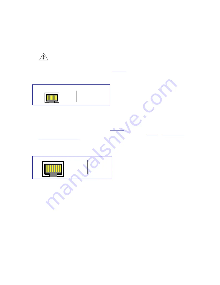
RJ-48c trunk connectors are wired according to
.
Figure 2
Pinout of the RJ-48c Trunk Connectors
1 2 3 4 5 6 7 8
3, 6, 7, 8
not connected
body = shield
1 = Rx RING
2 = Rx TIP
4 = Tx RING
5 = Tx TIP
RJ-48c Connector and Pinout
3
Connect the first Ethernet connection (labeled
I
), located on the CPU module of the
V6100 front panel, directly to the network using a standard RJ-45 Ethernet cable (and
the second connection as optional redundancy / backup). Note that for redundant
operation it is recommended to connect each of the Ethernet connectors to a different
switch. For the connector’s pinout, refer to
.
When assigning an IP address to the V6100 using HTTP (under
in
), you may be required to disconnect this cable and re-cable it
differently.
Figure 3
RJ-45 Ethernet Connector Pinout
1 2 3 4 5 6 7 8
4, 5, 7, 8
not
connected
1 - Tx+
2 - Tx-
3 - Rx+
6 - Rx-
4
Using the supplied RS-232 cable connect the V6100 RS-232 port (Labeled I0I0) to either
COM1 or COM2 RS-232 communication port on your PC. Using the RS-232 port is
optional.
5
If you want to set up a dry contact system (future support), refer to the
V6100 Digital
Gateway User
Guide.
6
If you want to set up an audio system (future support), refer to the
V6100 Digital
Gateway User
Guide.
7
Connect the left (active) 100-240V~50-60 Hz power socket to the mains using the
supplied cord.
14
V6100 Digital Gateway Installation Guide


