background image

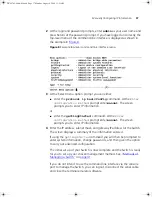
Viewing Automatically Configured IP Information

39

A suitable cable:

An RJ-45 to DB9 converter cable.

A standard null modem cable — if you are connecting directly to 
the console port, or

A standard modem cable — if you are connecting to the console 
port using a modem.

You can find pin-out diagrams for both cables in 

Appendix B

 on 

page 63

.

A Category 5 twisted pair Ethernet cable with RJ-45 connectors to 
connect your Switch to the network.

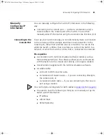
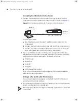
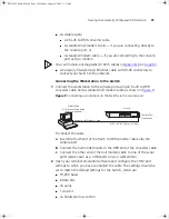
Connecting the Workstation to the Switch

1

Connect the workstation to the console port using an RJ-45 to DB9 
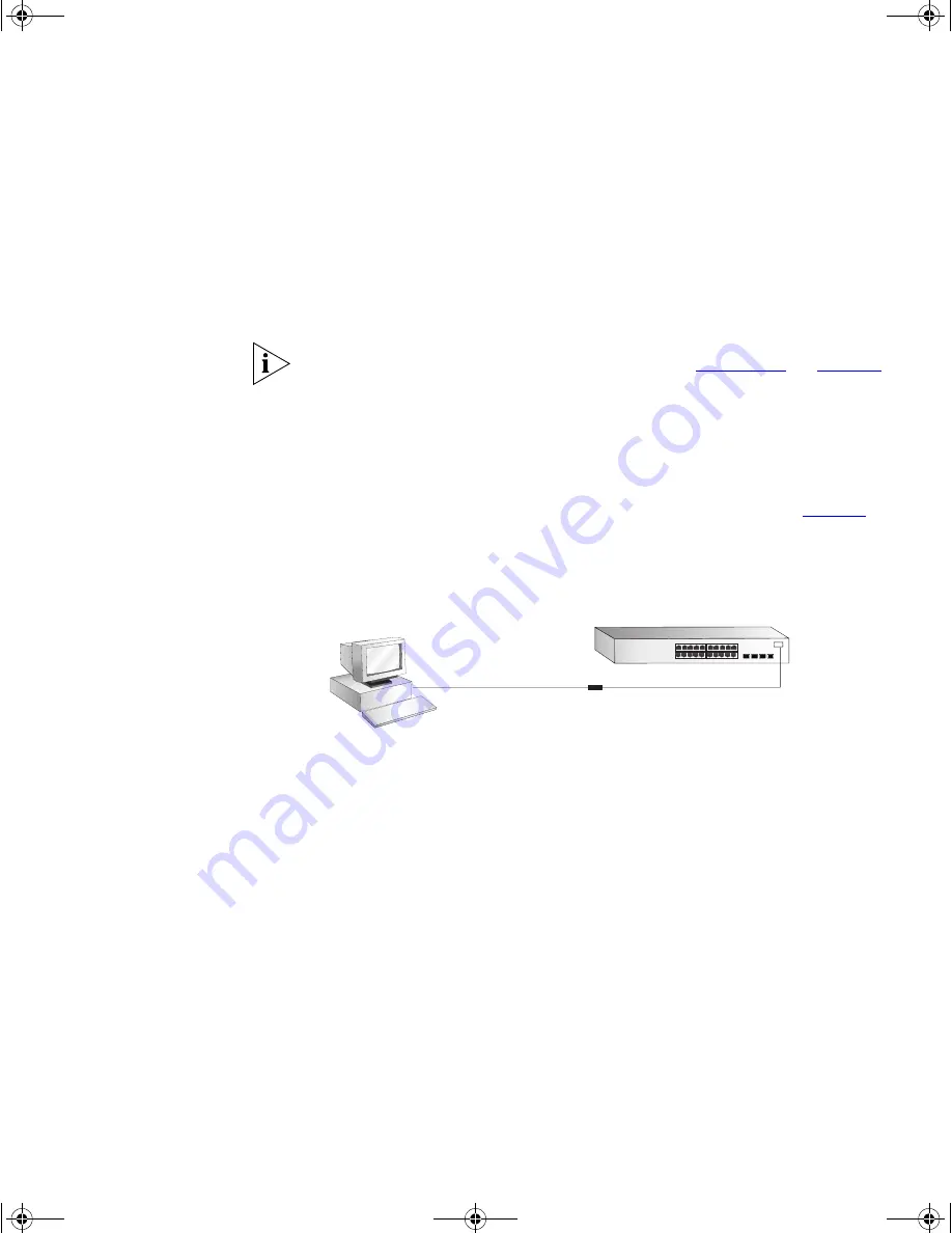
converter cable and a standard null modem cable as shown in 

Figure 9

.

Figure 9 

Connecting a workstation to the Switch via the console port

To connect the cable:

a

Insert the RJ-45 end of the RJ-45 to DB9 converter cable into the 
console port.

b

Connect the null modem cable to the DB9 end of the converter cable.

c

Connect the other end of the null modem cable to one of the serial 
ports (also known as a COM port) on your workstation.

2

Open your terminal emulation software and configure the COM port 
settings to which you have connected the cable. The settings should be 
set to match the default settings for the Switch, which are: 

19,200 baud

8 data bits

no parity

1 stop bit

no hardware flow control

Console Port

Connection

Workstation

(with terminal emulation

software installed)

Switch

Standard Null Modem Cable

RJ-45 to DB9  Converter Cable

DUA1745-0AAA02.book  Page 39  Monday, August 9, 2004  11:51 AM

Summary of Contents for SUPERSTACK 3 3870 Series

Page 1: ...http www 3com com Part No DUA1745 0AAA02 Published August 2004 SuperStack 3 Switch 3870 Family Getting Started Guide 3CR17450 91 3CR17451 91 DUA1745 0AAA02 book Page 1 Monday August 9 2004 11 51 AM...

Page 2: ...of any legend provided on any licensed program or documentation contained in or delivered to you in conjunction with this User Guide Unless otherwise indicated 3Com registered trademarks are register...

Page 3: ...SE TX 1000BASE T Ports 14 Dual Personality SFP Ports 14 Console Port 14 LEDs 15 Switch 3870 Rear View Detail 17 Expansion Module Slot 17 Power Socket 17 Redundant Power System Socket 17 Stacking Cable...

Page 4: ...ecting to the Console Port 38 Methods of Managing a Switch 41 Command Line Interface Management 41 Web Interface Management 42 SNMP Management 42 Setting Up Command Line Interface Management 42 CLI Ma...

Page 5: ...ble 63 Modem Cable 64 RJ 45 Pin Assignments 64 C TECHNICAL SPECIFICATIONS Switch 3870 67 D OBTAINING SUPPORT FOR YOUR PRODUCT Register Your Product to Gain Service Benefits 69 Purchase Value Added Ser...

Page 6: ...DUA1745 0AAA02 book Page 6 Monday August 9 2004 11 51 AM...

Page 7: ...es you detailed information on how to use the web interface and command line interface to manage the Switch Other documentation relating to the 3Com SuperStack 3 Switch 3870 3Com Network Supervisor a...

Page 8: ...use the following syntax system password password In this example you must supply a password for password Commands The word command means that you must enter the command exactly as shown and then pres...

Page 9: ...that accompanies the Switch Management Interface Reference Guide This guide provides detailed information about the web interface and command line interface that enable you to manage the Switch It is...

Page 10: ...tation is accessed using the index htm file The PDF Implementation Guide is stored in the Docs implementation directory of the CD ROM 3Com recommends that you copy the Docs referenceguide directory as...

Page 11: ...about the Switch 3870 and how it can be used in your network It covers summary information about the hardware and the following topics About the Switch 3870 Switch 3870 Front View Detail Switch 3870 R...

Page 12: ...panies the Switch Summary of Hardware Features Table 3 summarizes the hardware features that are supported by the Switch 3870 Table 3 Hardware features Feature Switch 3870 MAC Addresses Up to 16 000 s...

Page 13: ...24 port Stack Master Module Activity Port Status LEDs Power Self Test LED Unit LED 21 22 23 24 Dual Personality 10 100 1000BASE T 1000BASE X SFP Ports Fault LED Module Status LED Module Activity LED S...

Page 14: ...s Dual Personality SFP Ports The 4 Dual Personality SFP Small Form Factor Pluggable ports support fiber Gigabit Ethernet short wave SX long wave LX and long haul LH70 transceivers in any combination T...

Page 15: ...tive Green for one second Amber for one second then OFF until operational POST in operation all LEDs perform a one second lamp test Alternate yellow then green flashing fast A port has failed a loop b...

Page 16: ...cked and the position within the stack is displayed Off The Switch is not stacked Power Self Test LED Green The Switch is powered up and operating normally Green flashing The Switch is either download...

Page 17: ...Advanced Redundant Power System See Connecting a Redundant Power Supply on page 25 Stacking Cable Ports You can use these ports to connect the following cables Stacking Cable 3C17462 which enables you...

Page 18: ...lt Settings Type of Unit Total Units in the Stack Maximum Modules 48 Port 24 Port 0 8 8 8 8 0 8 0 7 1 8 2 7 0 7 4 6 2 8 4 6 1 7 6 6 0 6 6 Feature Switch 3870 Port Status Enabled Port Speed Auto negoti...

Page 19: ...ze in the Command Line Interface the following settings are retained to allow you to connect to and manage the Switch IP Address Subnet Mask Default Gateway Link Aggregation Control Protocol LACP Disa...

Page 20: ...20 CHAPTER 1 INTRODUCING THE SUPERSTACK 3 SWITCH 3870 DUA1745 0AAA02 book Page 20 Monday August 9 2004 11 51 AM...

Page 21: ...u must read the safety information provided in Appendix A of this guide AVERTISSEMENT Consignes de s curit Avant d installer ou d enlever tout composant de Switch 3870 ou d entamer une proc dure de ma...

Page 22: ...s have a high audible output while running at full speed The Switch 3870 is designed to reduce the fan speed shortly after power on if thermal conditions allow which will also reduce the fan noise gen...

Page 23: ...one another if the units are free standing Rack mounting The Switch 3870 is 1U high and will fit in most standard 19 inch racks CAUTION Disconnect all cables from the Switch before continuing Remove...

Page 24: ...holes are not obstructed 6 Connect network cabling Placing Units On Top of Each Other If the Switch units are free standing up to four units can be placed one on top of the other If you are mixing a...

Page 25: ...s operating correctly Table 7 shows possible colors for the LED Table 7 Unit Status Colors If there is evidence of a problem see Solving Problems Indicated by LEDs on page 48 for a list of suggested s...

Page 26: ...s over cable MDIX The Auto MDIX feature only operates when auto negotiation is enabled If auto negotiation is disabled all the Switch ports are configured as MDIX cross over If you want to make a conn...

Page 27: ...transceivers are hot insertable and hot swappable You can remove them from and insert them into any SFP port without having to power down the Switch Approved SFP Transceivers The following list of app...

Page 28: ...ed correctly It is not necessary to power down your Switch 2 Hold the transceiver so that the connector is toward you and the product label is visible Ensure the wire release lever is closed in the up...

Page 29: ...ormation Removing an SFP Transceiver If you wish to remove the transceiver it is not necessary to power down your Switch 1 Disconnect the cable from the transceiver 2 Move the wire release lever downw...

Page 30: ...30 CHAPTER 2 INSTALLING THE SWITCH DUA1745 0AAA02 book Page 30 Monday August 9 2004 11 51 AM...

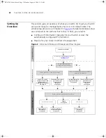
Page 31: ...to improve the efficiency of the Switch and therefore the overall performance of your network This chapter explains the initial set up of the Switch and the different methods of accessing the managem...

Page 32: ...wer Up the Switch IP Information is automatically configured See page 33 Do you want to manually configure the IP information Connect to a front panel port and use the Web Interface or Command Line In...

Page 33: ...you to allocate static IP addresses Static IP addresses are necessary to ensure that the Switch is always allocated the same IP information For most installations 3Com recommends that you configure t...

Page 34: ...with an appropriate IP address instead of you having to manually reconfigure the Switch If you use the automatic IP configuration method you need to discover the automatically allocated IP informatio...

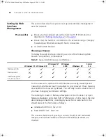
Page 35: ...t the Switch to a network or whilst the Switch is online that is connected to a network Pre requisites A workstation with terminal emulation software installed such as Microsoft Hyperterminal This sof...

Page 36: ...t settings to which you have connected the cable The settings should be set to match the default settings for the Switch which are 19 200 baud 8 data bits no parity 1 stop bit no hardware flow control...

Page 37: ...ion method prompt enter manual The screen prompts you to enter IP information 4 Enter the IP address subnet mask and gateway IP address for the Switch The screen displays a summary of the information...

Page 38: ...Com Network Supervisor and run the Auto discovery wizard 3Com Network Supervisor will auto discover the new Switch and display the IP information that has been automatically allocated to the Switch Mo...

Page 39: ...9 Connecting a workstation to the Switch via the console port To connect the cable a Insert the RJ 45 end of the RJ 45 to DB9 converter cable into the console port b Connect the null modem cable to th...

Page 40: ...equence begins as soon as the Switch detects a connection to its console port If the login prompt does not begin immediately press Return a few times until it starts 3 At the login and password prompt...

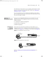
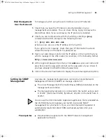
Page 41: ...ollowing methods Command line interface management Web interface management SNMP management Command Line Interface Management Each Switch has a command line interface CLI that allows you to manage the...

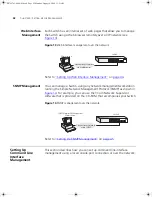
Page 42: ...anagement Protocol SNMP as shown in Figure 14 For example you can use the 3Com Network Supervisor software that is provided on the CD ROM that accompanies your Switch Figure 14 SNMP management over th...

Page 43: ...g a ping command at the DOS prompt in the following format c ping xxx xxx xxx xxx where xxx xxx xxx xxx is the IP address of the Switch If you get an error message check that your IP information has b...

Page 44: ...ectly JavaScript and Cascading Style Sheets must be enabled on your browser These features are enabled on a browser by default You will only need to enable them if you have changed your browser settin...

Page 45: ...ts enter admin as your user name and press Return at the password prompt or the password of your choice if you have already modified the default passwords 5 Click on the Device View button to display...

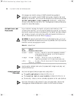
Page 46: ...hree default passwords as soon as possible even if you do not intend to actively manage your Switch Table 10 Default Users Use the admin default user name no password to login and carry out initial Sw...

Page 47: ...Indicated by LEDs Solving Hardware Problems Solving Communication Problems Solving Software Upgrade Problems If you experience a problem that is not listed here it may be included in the support sect...

Page 48: ...does not light Check that the power cable is firmly connected to the Switch and to the supply outlet If the connection is secure and there is still no power you may have a faulty power cord or an inte...

Page 49: ...even if one or more ports are disabled A link is connected and yet the Port Status LED for the port does not light Check that The Switch and the device at the other end of the link or cable are connec...

Page 50: ...ded through the Device Summary table for the specific unit In addition all Summary tables turn red to indicate the fan failure The device mimic will also display red flashing fan icons For further inf...

Page 51: ...al Support Solving Communication Problems If you experience communication problems with the Switch ensure that The Switch IP address has been configured If the Switch is separated from your management...

Page 52: ...ll not operate correctly InterNIC Registration Services is the organization responsible for supplying registered IP addresses The following contact information is correct at time of publication World...

Page 53: ...he system control softwareUpgrade command in the command line interface For details on these options refer to the Management Interface Reference Guide supplied in HTML format on the CD ROM that accomp...

Page 54: ...54 CHAPTER 4 PROBLEM SOLVING DUA1745 0AAA02 book Page 54 Monday August 9 2004 11 51 AM...

Page 55: ...issements pr sentent des consignes que vous devez respecter pour garantir votre s curit personnelle Vous devez respecter attentivement toutes les consignes Nous vous demandons de lire attentivement le...

Page 56: ...ce inlet U S A and Canada The cord set must be UL approved and CSA certified The minimum specification for the flexible cord is No 18 AWG Type SV or SJ 3 conductor The cord set must have a rated curre...

Page 57: ...elled Neutral connected directly to earth ground Imp dance la terre WARNING U K only If connecting a modem to the console port of the Switch 3870 only use a modem which is suitable for connection to t...

Page 58: ...sions L information de S curit Importante AVERTISSEMENT L installation et la d pose de ce groupe doivent tre confi s un personnel qualifi AVERTISSEMENT Si vous entassez l unit Switch avec les unit s S...

Page 59: ...terre Si vos alimentations sont du type imp dance la terre ce groupe doit tre aliment par une tension de 230 V 2 P T par le biais d un transformateur d isolement rapport 1 1 avec un point secondaire d...

Page 60: ...s avec des jacks prot g s ou non prot g s ces prises de donn es AVERTISSEMENT Si le module d expansion nest pas install veillez bien installer la plaque d obturation et serrez toutes les vis l aide d...

Page 61: ...Der Ger testecker der Anschlu an das Ger t nicht der Wandsteckdosenstecker mu eine passende Konfiguration f r einen Ger teeingang gem EN60320 IEC320 haben VORSICHT Die Netzsteckdose mu in der N he de...

Page 62: ...angeschlossen werden VORSICHT Ist kein Erweiterungsmodul installiert berpr fen Sie bitte den Sitz der Stanzplatte indem Sie alle Schrauben mit einem geeigneten Werkzeug anziehen VORSICHT Faseroptikan...

Page 63: ...5 pin male female only required if screen always required required for handshake Screen DTR TxD RxD CTS Ground DSR RTS DCD Screen DCD RxD TxD DTR Ground DSR RTS CTS Shell 4 3 2 8 5 6 7 1 Shell 1 2 3 4...

Page 64: ...7 8 20 Switch 3870 Cable connector RJ 45 female RS 232 Modem Port Cable connector 25 pin male Pin Number 10 100 1000 Ports configured as MDI 1 Transmit Data Bidirectional Data A 2 Transmit Data Bidir...

Page 65: ...nal Data B 2 Receive Data Bidirectional Data B 3 Transmit Data Bidirectional Data A 4 Not assigned Bidirectional Data A 5 Not assigned Bidirectional Data D 6 Transmit Data Bidirectional Data D 7 Not a...

Page 66: ...66 APPENDIX B PIN OUTS DUA1745 0AAA02 book Page 66 Monday August 9 2004 11 51 AM...

Page 67: ...paras 2 1 2 2 2 30 and 2 32 Operational testing paras 2 1 2 2 2 30 and 2 13 Safety Agency Certifications UL 60950 EN60950 CSA 22 2 No 60950 IEC 60950 IEC825 1 EN60825 1 EMC Emissions CISPRR 22 Class...

Page 68: ...esting paras 2 1 2 2 2 30 and 2 32 Operational testing paras 2 1 2 2 2 30 and 2 13 Safety Agency Certifications UL 60950 EN60950 CSA 22 2 No 60950 IEC 60950 IEC825 1 EN60825 1 EMC Emissions CISPRR 22...

Page 69: ...rt software upgrades onsite assistance or advance hardware replacement Experienced engineers are available to manage your installation with minimal disruption to your network Expert assessment and imp...

Page 70: ...rsion included with your original product In order to access upgrades and related documentation you must first purchase a service contract from 3Com or your reseller Contact Us 3Com offers telephone e...

Page 71: ...98 61 2 9937 5083 Philippines P R of China Singapore S Korea Taiwan Thailand 1235 61 266 2602 or 1800 1 888 9469 10800 61 00137 or 021 6350 1590 or 00800 0638 3266 800 6161 463 080 333 3308 00801 611...

Page 72: ...Salvador Trinidad and Tobago Uruguay Venezuela Virgin Islands AT T 800 998 2112 57 1 657 0888 AT T 800 998 2112 1 800 998 2112 571 657 0888 01 800 849CARE AT T 800 998 2112 AT T 800 998 2112 54 11 489...

Page 73: ...2 IP configuration 33 L LEDs 15 logging in as a default user 46 M management methods 41 preparing for 34 setting up 31 32 manual setup console port 35 MDI configuration 26 MDIX configuration 26 P pass...

Page 74: ...king cable ports 17 straight through configuration 26 Switch automatic setup 38 Switch 3870 dimensions 67 features 12 installation 21 23 powering up 25 rack mounting 23 size 67 weight 67 system specif...

Page 75: ...nd receiver are on different branch circuits If necessary the user should consult the dealer or an experienced radio television technician for additional suggestions The user may find the following bo...

Page 76: ...DUA1745 0AAA02 book Page 76 Monday August 9 2004 11 51 AM...

Reviews: