background image

2

C

ORE

B

UILDER

® 

5000 S

WITCH

M

ODULE

 Q

UICK

  S

TART


AND

  R

EFERENCE


3

Ensure that the CoreBuilder 5000 hub contains either a 
PacketChannel or a SwitchChannel backplane. 

To verify that the hub has one of these backplanes, 
enter the command SHOW HUB. The model number 
displayed in the Hub Type field should end in C 
(SwitchChannel) or P (PacketChannel), and one of these 
backplanes should be listed under Backplane Type.

For example:

show hub

Hub Information:

Hub Type: 6017C-AC

Backplane Information:

Backplane Type

Revision

--------------

--------

Load-Sharing Power Distribution module

0

Enhanced TriChannel Backplane

1

RingChannel Backplane

0

SwitchChannel Backplane

2

If your hub does not have an installed PacketChannel or 
SwitchChannel backplane and you require 
communication among SwitchModules, contact 3Com 
or your 3Com representative to order a backplane 
upgrade kit. 

4

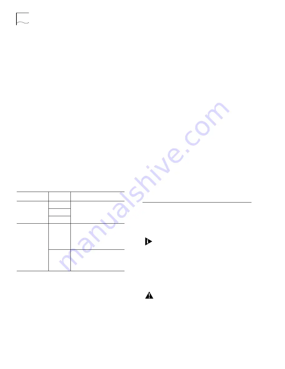
Use the following table to determine the slot 
restrictions that apply to your hub configuration: 

If you are installing 

only one

 SwitchModule, you can 

install it in any slot, including a reserved ATM slot. The 
single SwitchModule acts as a stand-alone switch.

If your hub does not have an installed PacketChannel or 
SwitchChannel backplane, you can install only one 
SwitchModule per hub.

Backplane Type

 Hub Type

Installation Guideline

PacketChannel

17-Slot

Install SwitchModules in any 
slot.

10-Slot

7-Slot

SwitchChannel 
(PacketChannel 
plus ATM 
Cell-Switching)

17-Slot

Slots 9, 10, 11, and 12 are 
reserved for the 
CoreBuilder

®

5000 ATM 

Switch/Control Point Module 
(Model Number 3C96416SW).

10-Slot

Slots 9 and 10 are reserved for 
the CoreBuilder 5000 ATM 
Switch/Control Point Module 
(Model Number 3C96416SW).

3.3

Software Prerequisites

Before you install a new SwitchModule:

1

Determine the DMM module’s software version status. 
Enter the SHOW MODULE ALL command. 

show module all

The following display appears:

Slot

Module

Version

Network

General Info

----- -------

-------

-------- -------------

10.01 6100D-MGT

v1.00

ETHERNET_1

11.01 6000M-RCTL

v1.15

N/A

Active

Ctrl Module

12.01 6000M-ARCTL

v1.15

N/A

Stndby Ctrl

Module

12.02 6000M-AMGT

v6.00

N/A

Master Mgmt

Module

2

Look in the Version column to get the DMM software 
version. The new SwitchModule functions incorrectly if 
the DMM software version is wrong.

As shown in the previous display example, the 
Advanced DMM/Controller (Model 
Number 6000M-CMGT) appears as two modules in the 
same slot (Model Numbers 6000M-ARCTL and 
6000M-AMGT). The DMM operational code version is 
displayed in the Version field of the -AMGT module.

4.0

Crucial Download Procedure

Review the following procedures before you attempt to 
download software to any SwitchModule in your hub. 

You must use the following procedures if you have 
66xx family SwitchModules installed in your hub.

4.1

Download Procedure for SwitchModules 
Earlier than Version v2.02 and DMMs 
Earlier than Version v5.00 

Use the following procedure for all SwitchModules in your 
hub that are earlier than Version v2.02, and DMMs that 
are earlier than Version v5.00. 

CAUTION: 

All bridge port communication ceases if 

you use an incorrect download procedure to 
upgrade your SwitchModule and Distributed 
Management Module (DMM) and Advanced DMM 
(A/DMM) software. If you use an IP relay for 
connectivity to download code to the DMM, that 
connection also stops. 

Summary of Contents for CoreBuilder 5000

Page 1: ...r later CoreBuilder 5000 Distributed Management Module Commands Guide for software Version v6 00 or later You can view these documents online with the 3Com DocsOnCD documentation CD ROM that comes wit...

Page 2: ...416SW 10 Slot Slots 9 and 10 are reserved for the CoreBuilder 5000 ATM Switch Control Point Module Model Number 3C96416SW 3 3 Software Prerequisites Before you install a new SwitchModule 1 Determine t...

Page 3: ...0 operational code to all SwitchModules in the hub 3 Download ATM SwitchModule software Version v3 00 operational code to all ATM Backbone SwitchModules in the hub The ATM SwitchModule model number is...

Page 4: ...tchModule User Guide CoreBuilder 5000 SwitchModule Quick Start and Reference this guide CoreBuilder 5000 SwitchModule Command Reference CoreBuilder 5000 SwitchModule Planning Chart CLASS 1 LED PRODUCT...

Page 5: ...t panel with one hand while you close each ejector handle Ensure that the SwitchModule remains fully seated in the backplane connector while you close the ejector handles 5 To secure the SwitchModule...

Page 6: ...col is enabled on virtual bridge 1 and on all SwitchModule ports Spanning Tree parameters are set to their default settings which are described in Chapter 7 in the CoreBuilder 5000 SwitchModule User G...

Page 7: ...able the existing in band DMM interface SwitchModules in slots 2 3 and 4 NMS LAN DMM in slot 1 For more information about IP configuration see the CoreBuilder 5000 SwitchModule User Guide on the DocsO...

Page 8: ...th this product You can also use a network management application such as 3Com Transcend Network Control Services to further configure SwitchModules See the appropriate network management documentatio...

Page 9: ...in chassis and connected to the PacketChannel backplane Off SwitchModule is not connected to the PacketChannel backplane or was inserted in slots 9 12 17 slot hub or 9 and 10 10 slot hub which are res...

Page 10: ...o connectors with 12 ports per connector for a total of 24 ports The following illustrations show these SwitchModules The X that follows the port numbers indicates a crossover port Port Status Activit...

Page 11: ...lows the port number indicates a crossover port CoreBuilder 5000 10BASE T modules use crossover ports This means that if you connect a 10BASE T SwitchModule port to another CoreBuilder 5000 10BASE T m...

Page 12: ...enabled and link is OK 1 Blink No light on receive fiber 2 Blinks Port received jabber 3 Blinks Port is partitioned 4 Blinks Remote fault Off Port or port functions are disabled Yellow On Heavy traff...

Page 13: ...On Port is enabled and link is OK Green Blinking Link failure or waiting for network connection Off Port or port functions are disabled Yellow On Heavy port traffic activity Yellow Blinking Normal po...

Page 14: ...dule is a Dual Attachment Concentrator DAC which is composed of 4 M ports and an A and B port pair that is connected to a single MAC 15 3 Optical Bypass Connector FDDI SwitchModules support one optica...

Page 15: ...Port is in full duplex mode Green Blinking Autonegotiation is determining the correct duplex setting Off Port is in half duplex mode Copyright 3Com Corporation 2000 All rights reserved 3Com the 3Com l...

Page 16: ...xhibits a defect in materials or workmanship within the first forty eight 48 hours of installation but no later than thirty 30 days after the date of purchase and this is verified by 3Com it will be c...

Reviews: