background image

Configuring VLANs

47

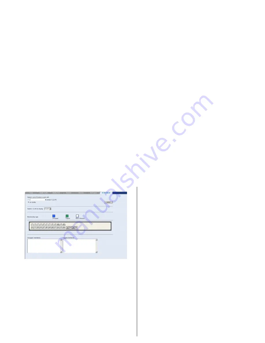
Figure 30   

VLAN Detail Screen

Forwarding Tagged/Untagged Frames

Each port on the Switch is capable of passing 
tagged or untagged frames.

The following describes how the Switch will 
handle tagged and untagged frames.

When a port receives a tagged frame with a 
VLAN ID and the port is a member 
(untagged or tagged) of that VLAN, the 
frame is accepted. Otherwise the if the port 

is not a member of that VLAN, the frame is 
discarded.

When a port receives an untagged frame 
and the port is an untagged member of a 
VLAN, the frame is accepted and assigned to 
that VLAN ID. Otherwise if the port is not an 
untagged member of any VLAN, the frame is 
discarded.

The Switch will only forward a frame to ports 
that are members (tagged or untagged) of the 
VLAN to which the frame is assigned. If the 
port is an untagged member, the egress frame 
will be stripped of the VLAN tag and forwarded 
as untagged. However, if the port is a tagged 
member, the egress frame is forwarded as 
tagged.

Sample VLAN Configurations

To illustrate how you can segment network 
devices that are connected to the Switch, the 
following sample configurations are provided.

Summary of Contents for Baseline 2226 Plus

Page 1: ...www 3com com Part No 10015240 Rev AA Published August 2006 Baseline Switch 2226 Plus User Guide Installationsanleitung 3C16475CS...

Page 2: ...ree not to remove or deface any portion of any legend provided on any licensed program or documentation contained in or delivered to you in conjunction with this User Guide Unless otherwise indicated...

Page 3: ...f Each Other 17 Supplying Power to the Switch 18 Checking for Correct Operation 18 Using SFP Tranceivers 19 Approved SFP Transceivers 19 Inserting an SFP Transceiver 19 Removing an SFP Transceiver 20...

Page 4: ...rroring 61 Statistics 62 QoS VoIP Traffic Settings 62 Security 65 RADIUS Client 65 802 1X Settings 67 Monitoring 70 Address Table 70 Cable Diagnostics 70 5 TROUBLESHOOTING Resetting to Factory Default...

Page 5: ...GLOSSARY REGULATORY NOTICES INDEX...

Page 6: ......

Page 7: ...ks voraus If release notes are shipped with your product and the information there differs from the information in this guide follow the instructions in the release notes Most user guides and release...

Page 8: ...directed in the first instance to your network supplier Product Registration You can now register your Baseline Switch on the 3Com Web site to receive up to date information on your product http esupp...

Page 9: ...nt panel for easy flexible connection to fiber based Gigabit media Autosensing of MDI MDIX Connections All ports on the Switch can autosense both medium dependent interface MDI and medium dependent in...

Page 10: ...th shielded or unshielded jacks can be connected to these data sockets AVERTISSEMENT Points d acc s RJ 45 Ceux ci sont prot g s par des prises de donn es Ils ne peuvent pas tre utilis s comme prises d...

Page 11: ...e associated RJ 45 port of the same number is disabled The two SFP ports support fiber Gigabit Ethernet short wave SX and long wave LX SFP transceivers in any combination This offers you the flexibili...

Page 12: ...nit or the device connected to the port is faulty Contact your supplier for further advice Status Meaning Green The link is operating at 100 Mbps Yellow The link is operating at 10 Mbps Flashing Green...

Page 13: ...Only use the power cord that is supplied with the unit 8 Recovery Button The recovery button reinitializes the Switch This returns the Switch to the factory default settings if for example you have fo...

Page 14: ...itch package is complete The Switch comes with One power cord Four standard height self adhesive rubber pads One mounting kit Installation CD This User Guide Warranty flyer The Switch is powered from...

Page 15: ...de ce guide WARNHINWEIS Sicherheitsinformationen Bevor Sie Komponenten aus dem Switch entfernen oder dem Switch hinzufuegen oder Instandhaltungsarbeiten verrichten lesen Sie die Sicherheitsanweisungen...

Page 16: ...a ground point If one is not available try to keep in contact with a grounded rack and avoid touching the unit s ports and connectors if possible Static discharge can cause reliability problems in you...

Page 17: ...Entfernen Sie die selbstklebenden Polster F e von der Unterseite der Baugruppe falls diese bereits angebracht sind 1 Plazieren Sie die Baugruppe aufrecht auf einer harten ebenen Fl che mit der Vorders...

Page 18: ...urely connected CAUTION The Switch has no ON OFF switch The only way to power on and power off the Switch is by connecting and disconnecting the power cord This is called power cycling To power on the...

Page 19: ...hem from and insert them into any SFP port without having to power down the Switch Approved SFP Transceivers The following list of approved SFP transceivers is correct at the time of publication 3CSFP...

Page 20: ...y inserted only one way If the transceiver does not click when you insert it remove it turn it over and reinsert it 3 Remove the plastic protective cover if fitted 4 Connect the fiber cable 5 Attach a...

Page 21: ...om recommends periodically checking the items listed in Table 1 Table 1 Items to Check If you experience any problems operating the Switch refer to Troubleshooting on page 73 Cabling Check that all ex...

Page 22: ...22 INSTALLING THE SWITCH...

Page 23: ...and buttons that are available on the Web interface The following topics are covered Requirements for Accessing the Web Interface Running the Discovery Application Logging On to the Web Interface Navi...

Page 24: ...insert the CD ROM into its CD drive Discovery should start automatically If it does not start automatically go to the Discovery folder on the CD ROM and then double click discovery exe The Welcome sc...

Page 25: ...interface appears Logging On to the Web Interface After the Web interface loads in your Web browser the first page that appears is the logon screen On this screen you need to enter the administration...

Page 26: ...ced configuration tasks and view information about the Switch Menu The menu is located on the left side of the Web interface When you click an item on the menu the related screen appears in the main p...

Page 27: ...to restore a saved configuration Firmware Upgrade Allows you to upgrade the current firmware via HTTP Initialize Allows you to reset the Switch to factory default settings Reboot Allows you to perfor...

Page 28: ...ort Contains tabs that allow you to Display selected spanning tree information for every port Display individual port spanning tree information Modify the spanning tree settings for a port Menu Item D...

Page 29: ...the port on the image for the these following configuration options View detailed port information Configure the port settings View port statistics 802 1X Settings Contains tabs that allow you to Dis...

Page 30: ...he IP address that the Switch will assign to itself during auto IP configuration check the sticker on the base of the Switch This sticker contains the MAC address and default IP address of the Switch...

Page 31: ...h you do not need to access the Web interface and configure the Switch You only need to access the Web interface if you want to Set the administration password to the Web interface Assign an IP addres...

Page 32: ...om Version and Hardware Version Figure 8 Device View If you request for technical assistance from 3Com Support you may be asked to print out the information on this screen Polling Interval Enter the i...

Page 33: ...o enable devices on the network to communicate with the Switch you need to assign an IP address to it either by DHCP or by assigning a static IP address By default the Switch performs automatic IP con...

Page 34: ...address The Switch also assigns the subnet mask 255 255 0 0 default class B mask to itself 2 If this default IP address is already in use on the network then the Switch detects this and increments th...

Page 35: ...kup Configuration screen appears Figure 12 Backup Configuration 2 Click OK You will be prompted to provide a location where the configuration file will be saved Restore Configuration To reload configu...

Page 36: ...the Switch the Switch will restart and apply the newer system firmware version Figure 14 Upgrade Screen 1 Click Administration then Firmware Upgrade on the menu The Firmware Upgrade screen appears 2 O...

Page 37: ...witch to factory default settings 1 Click Administration then Initialize on the menu You will lose all your configuration changes The Switch LAN IP address will revert to the default IP address 169 25...

Page 38: ...ensure that unauthorized users do not access the Web interface 3Com recommends that you set an admin password when you first configure the Switch Even if you do not intend to actively manage the switc...

Page 39: ...User This page allows you to create a user and define the access level and password for that user Figure 16 Create User Screen Modify User This page allows you to modify a user s access level and pass...

Page 40: ...Figure 19 System Time Screen SNMP Simple Network Management Protocol SNMP is a communication protocol designed specifically for managing devices on a network Equipment commonly managed with SNMP incl...

Page 41: ...plays the list community access strings Figure 20 SNMP Summary Screen Setup Enable or disable the SNMP Agent Status Figure 21 SNMP Setup Screen SNMP Add This page allows you to create community string...

Page 42: ...e the Switch to create VLANs to organize any group of ports into separate broadcast domains VLANs confine broadcast traffic to the originating group and help eliminate broadcast storms in large networ...

Page 43: ...es you must specify a VLAN ID for each VLAN Figure 24 Setup Screen Available option on the Setup screen include VLAN ID ID of configured VLAN 1 4094 no leading zeroes For examples on setting up VLANs...

Page 44: ...s and configure the port to communicate with all other VLANs or a selected VLAN Figure 25 Modify VLAN Screen 1 Enter a set of VLANs or select all VLANs to configure then click Select 2 From the drop d...

Page 45: ...ged Untagged 2 Select a port to associate with the membership 3 Enter a VLAN to apply these changes to then click Apply Rename Use the Rename screen to change the name of a VLAN Figure 27 Rename Scree...

Page 46: ...tton to select all the VLANs Click Remove to remove the VLAN Port Detail Choose a port to display the tagged and untagged VLAN memberships it is associated with Figure 29 Port Detail Screen VLAN Detai...

Page 47: ...untagged frame and the port is an untagged member of a VLAN the frame is accepted and assigned to that VLAN ID Otherwise if the port is not an untagged member of any VLAN the frame is discarded The Sw...

Page 48: ...2 Refer to Setup for instructions VLAN1 is the default VLAN and already exists 2 Set ports 1 3 and 26 to associate with the Untagged membership in VLAN2 3 Click Apply Ports 1 3 and 26 now belong to V...

Page 49: ...Switch 2 set the ports that you want to be part of VLAN2 to Untagged Set one port for example port 8 to Tagged Click Apply 4 Connect the Tagged port on Switch 1 in this example port 16 to the Tagged p...

Page 50: ...est the Root Bridge and it is used for receiving the BPDUs initiated by the Root Bridge If a bridge does not get a Hello BPDU after a predetermined interval the bridge assumes that the link to the Roo...

Page 51: ...his procedure is called multicast filtering The purpose of IP multicast filtering is to optimize a switched network s performance so multicast packets will only be forwarded to those ports containing...

Page 52: ...pically with wrong answers that start the process over again Broadcast storms use substantial network bandwidth and may cause network time outs The settings include Status Enables and disables broadca...

Page 53: ...status of each port or shut down or disable ports The Port menu includes five items Administration Link Aggregation Spanning Tree per Port Port Mirroring Statistics Administration Three tabs are avail...

Page 54: ...han a receiving device can process If flow control is disabled packets may be dropped under certain periods of high traffic Flow control is disabled by default Speed Sets the speed mode of the port Av...

Page 55: ...ly setting a port to full duplex verify that the device connected to the port is also manually set to the same speed and duplex setting If connecting link partners are left to autonegotiate for a link...

Page 56: ...o work the trunks must be configured on both ends switches Guidelines for Creating Trunks Any port on the Switch can be used for creating a trunk This switch supports a maximum of four trunks Each tru...

Page 57: ...oup membership Figure 41 Link Aggregation Create Screen To create a new link aggregation group 1 Enter a link aggregation group ID in the box field 2 Select the ports to add to the goup 3 Click Apply...

Page 58: ...panning tree is a bridge based system for providing fault tolerance on networks and can be used to detect and disable network loops The spanning tree ensures that the optimal path is maintained betwee...

Page 59: ...y After all the bridges on the network have determined the configuration of their ports each bridge only forwards traffic between the Root Port and the ports that are the Designated Bridge Ports for e...

Page 60: ...between Point to Point Shared or Auto for the link type Path Cost The path cost is used to determine the best path between devices The path cost method is used to determine the range of values that ca...

Page 61: ...ION The analyzer port should have a higher bandwidth than the mirror port Otherwise the Switch may not be able to copy all traffic effectively during periods of high traffic Figure 47 Port Mirroring S...

Page 62: ...he Web interface Click Port then Statistics on the menu The Port Statistics Screen appears 2 Select the a port and enter a refresh interval 3 Click Apply QoS VoIP Traffic Settings Using the Web interf...

Page 63: ...VLAN for the switch Voice VLAN ID Input the Voice VLAN ID for the switch Voice VLAN Aging Time Input the aging time You must first create a VLAN from the VLAN Setup page before you can assign and conf...

Page 64: ...e to apply these settings to 3 Click Apply Figure 51 QoS Port Setup Screen Port Detail Use the Port Detail tab to display the Voice VLAN information for selected ports Figure 52 QoS Port Detail Screen...

Page 65: ...UI list 1 Enter a Telephony OUI and description 2 Click Add To remove an OUI from the list 1 Select a Telephony OUI from the list 2 Click Remove Figure 54 QoS OUI Modify Screen Security Using the Web...

Page 66: ...to a switch The RADIUS Client menu includes two tabs Detail Configure Detail Use the Detail tab to display the RADIUS Client settings Figure 55 RADIUS Client Detail Screen Configure Use the Configure...

Page 67: ...Figure 56 RADIUS Client Configure Screen 802 1X Settings The IEEE 802 1X dot1x standard defines a port based access control procedure that prevents unauthorized access to a network by requiring users...

Page 68: ...etup Use the Setup tab to configure the 802 1X authenticaion settings The following fields are available System Authentication Sets the global setting for 802 1X Default Disabled Operation Mode Allows...

Page 69: ...Re authentication Period Re authentication can be used to detect if a new device is plugged into a switch port Default Disabled Max Count The maximum number of hosts that can connect to a port when th...

Page 70: ...le Diagnostics Address Table Use the Address Table Summary screen to display the Address Table information You can query by selecting a port choosing a VLAN or entering in a MAC Address then click Sel...

Page 71: ...esult Cable Fault Distance or Last Update for every port on the switch Figure 61 Cable Diagnostic Summary Screen Diagnostics Use the Diagnostics tab to display individual port information on Test Resu...

Page 72: ...72 CHAPTER 4 CONFIGURING THE SWITCH...

Page 73: ...ou can reset the Switch to factory defaults CAUTION Resetting the Switch to factory defaults erases all your settings You will need to reconfigure the Switch after you reset it To reset the Switch to...

Page 74: ...ssigned to the Switch and you need to access the Web interface use the Discovery applica tion to automatically detect the IP address and connect to the interface For information on using the Discovery...

Page 75: ...eing used Refer to Approved SFP Transceivers on page 19 for details The equipment at the far end is installed and correctly configured The Link Activity LED is on but network performance is poor The S...

Page 76: ...t of broadcast frames to the network Some pieces of network equipment operate by sending out broadcast frames regularly Refer to the documentation that accompanies the device for information on disabl...

Page 77: ...e added services like 3Com ExpressSM and GuardianSM can include 24x7 telephone technical support software upgrades onsite assistance or advance hardware replacement Experienced engineers are available...

Page 78: ...ontact 3Com for assistance please have the following information ready Product model name part number and serial number Proof of purchase if you have not pre registered your product A list of system h...

Page 79: ...repair authorization number RMA by fax using this number 65 543 6348 Europe Middle East and Africa Telephone Technical Support and Repair From anywhere in these regions call 44 0 1442 435529 From the...

Page 80: ...12 AT T 800 998 2112 AT T 800 998 2112 AT T 800 998 2112 AT T 800 998 2112 AT T 800 998 2112 AT T 800 998 2112 AT T 800 998 2112 AT T 800 998 2112 AT T 800 998 2112 AT T 800 998 2112 AT T 800 998 2112...

Page 81: ...sions EN50081 1 EN 55022 Class A EN50082 1 IEC 1000 4 2 3 4 6 EN60555 2 Class A EN 60555 3 FCC Part 15 Subpart B Class A Immunity EN 55024 Operating Tempera ture 0 45 C 32 113 F Storage Tempera ture 4...

Page 82: ...82 APPENDIX B TECHNICAL INFORMATION...

Page 83: ...he 3Com Switch Family Safety and Regulatory Information manual included with this product You can find the 3Com Switch Family Safety and Regulatory Information manual on the product CD ROM that was in...

Page 84: ...84 APPENDIX C SAFETY INFORMATION...

Page 85: ...ly configure to use the best common speed The order of preference best first is 1000BASE T full duplex 100BASE TX full duplex 100BASE TX half duplex 10BASE T full duplex and 10BASE T half duplex Auto...

Page 86: ...o 1000 Mbps Category 6 Cables One of five grades of Twisted Pair TP cabling defined by the EIA TIA 568 B standard Category 6 can be used in Ethernet 10BASE T Fast Ethernet 100BASE TX and Gigabit Ether...

Page 87: ...IEEE Std 802 3 2002 IETF Internet Engineering Task Force An organization responsible for providing engineering solutions for TCP IP networks In the network management area this group is responsible f...

Page 88: ...ss associated with a particular network device Most devices that connect to a LAN have a MAC address assigned to them as they are used to identify other devices in a network MAC addresses are 6 bytes...

Page 89: ...that interconnects several LANs to form a single logical LAN that comprises of several LAN segments Switches are similar to bridges in that they connect LANs of a different type however they connect...

Page 90: ...es that share the same collision domain regardless of their physical location or connection point in the network A VLAN serves as a logical workgroup with no physical barriers and allows users to shar...

Page 91: ...ient the receiving antenna Relocate the equipment with respect to the receiver Move the equipment away from the receiver Plug the equipment into a different outlet so that equipment and receiver are o...

Page 92: ......

Page 93: ...8 CSA statement 91 D DHCP 86 diagram front panel 10 Discovery 23 dynamic host control protocol 86 E Ethernet 86 F Fast Ethernet 86 FCC statement 91 Feedback about this User Guide 8 forgotten IP addre...

Page 94: ...ubnet mask 89 Switch positioning 15 switch defined 89 T TCP IP 87 defined 89 technical specifications 81 traffic 89 monitoring 61 62 troubleshooting 73 forgotten IP address 74 forgotten password 74 LE...

Reviews: