PoE Power Rack Installation Guide
Chapter 4 Installation and Debugging
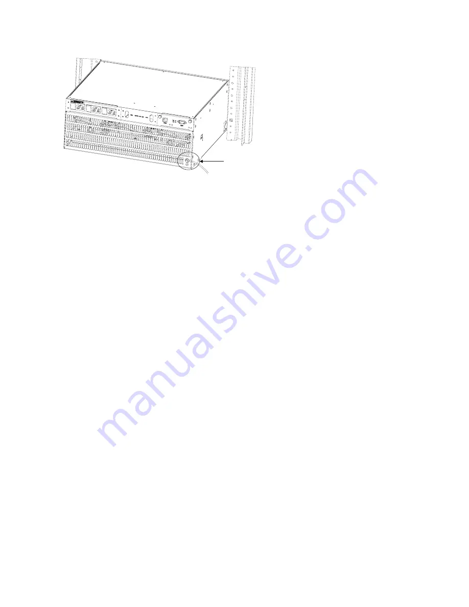
Frame Ground
Frame Ground
Figure 4-3
Frame grounding
DC Connection
The DC cable connections are connected to the PoE Power Rack and the Switch 7750 by heavy-duty type
terminal blocks.. The 0Volt (Return) DC cable must be connected to RTN (+) terminal and the -54Volt (negative )
DC cable must be connected to the "NEG (-)" negative terminal.
To connect the DC output cables to the PoE Power Rack:
1.) Insure AC power is removed from the PoE Power Rack before connecting the DC output cables.
2.) Using a #2 Philips screwdriver, remove the four Philips head screws that attach the DC terminal protector
plate from the PoE Power Rack.
3.) Insert the blue DC cable through the "NEG (-)" grommet hole on the DC terminal protector plate.
4.) Insert the black DC cable through the "RTN (+)" grommet hole on the DC terminal protector plate.
5.) Remove one 13 mm nut and washer from the "NEG (-)" DC terminal stud and attach the blue DC cable to
the "NEG (-)" terminal stud. Replace the washer on the terminal stud and securely fasten the 13 mm nut on
the DC terminal stud.
6.) Remove one 13 mm nut and washer from the "RTN (+)" DC terminal stud and attach the black DC cable to
the "RTN (+)" terminal stud. Replace the washer on the terminal stud and securely fasten the 13 mm nut on
the DC terminal stud.
7.) Replace the DC terminal protector plate and tighten the four Philips screws with the #2 Philips Screwdriver.
To connect the DC output cables to the Switch 7750:
1.) Insure AC power is removed from the PoE Power Rack before connecting the DC output cables.
2.) The DC terminal block for PoE input power is located on the back of the SWITCH 7750 chassis.
3.) Using a #2 Philips screwdriver, remove the two Philips head screws that attach the clear DC terminal block
cover from the SWITCH 7750.
4.) Remove one 10 mm nut and washer from the "NEG (-)" DC terminal stud and attach the blue DC cable to
4-4


