background image

Switch 4800G 24-Port

9

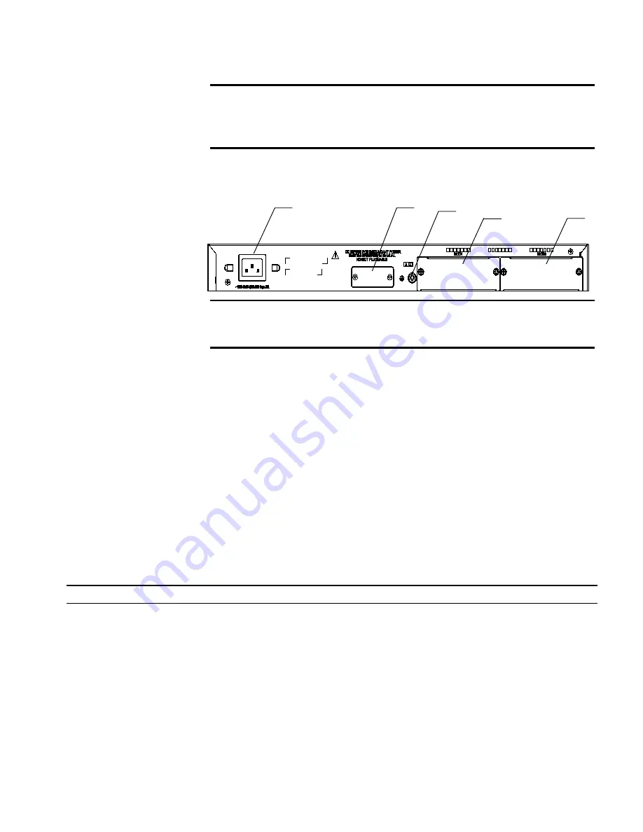
Rear Panel

Figure 3   

Rear panel of the Switch 4800G 24-Port

Power Supply System

The Switch 4800G 24-Port can adopt AC input, or 12 V RPS input, or both to 
provide backup. Only the recommended RPS can be used.

AC power input

Rated voltage range: 100 VAC to 240 VAC, 50 Hz or 60 Hz

Input voltage range: 90 VAC to 264 VAC, 47 Hz to 63 Hz

RPS input

Rated voltage range: 10.8 VDC to 13.2 VDC

Cooling System

The Switch 4800G 24-Port is equipped with four fans for heat dissipation.

LEDs

For descriptions about LEDs, see Table 4. You can switch the Mode LED display 
mode between speed and duplex by pressing the Mode button on the panel.

(3) Console port 

(4) 7-segment digital LED 

(5) Power LED 

(6) RPS LED 

(7) LED for extended module slot 1 

(8) LED for extended module slot 2 

(9) Mode LED 

(10) Mode button

(1) AC power socket 

(2) RPS port 

(3) Grounding screw 

(4) Extended module slot 1 

(5) Extended module slot 2 

(1)

(2)

(3)

(4)

(5)

(1)

(2)

(3)

(4)

(5)

Table 4   

LEDs on the front panel of the Switch 4800G 24-Port

LED Mark 

Status 

Description 

Mode LED 

Mode  Speed 

Solid green

Rate of the port 

Duplex 

Solid yellow

Duplex mode of the port 

Power LED 

PWR 

Solid green

The switch is started normally. 

Flashing green (1 Hz)

The system is running a power-on 
self-test (POST). 

Solid red

The system fails the POST or a power 
failure occurs. 

Flashing yellow (1 Hz)

Some ports fail a POST or a port 
failure occurs. 

OFF

The power is disconnected. 

Summary of Contents for 4800G Series

Page 1: ...Part Number 10016617 Rev AA Published April 2008 3Com Switch 4800G Family Getting Started Guide Switch 4800G 24 Port Switch 4800G PWR 24 Port Switch 4800G 48 Port Switch 4800G PWR 48 Port Switch 4800G...

Page 2: ...252 227 7015 Nov 1995 or FAR 52 227 14 June 1987 whichever is applicable You agree not to remove or deface any portion of any legend provided on any licensed program or documentation contained in or d...

Page 3: ...NSTALL THE SWITCH Safety Precautions 25 Installation Site 25 Installation Tools 27 3 INSTALLING THE SWITCH Installing the Switch into a 19 Inch Cabinet 29 Mounting the Switch on a Workbench 38 Connect...

Page 4: ...re 74 Configuration System Failure 74 A LIGHTNING PROTECTION FOR THE SWITCH Installating the Lightning Arrester for AC Power Socket Strip with Lightning Protection 75 Installation of Lightning Arreste...

Page 5: ...conventions that are used throughout this guide Related Documentation The following manuals offer additional information necessary for managing your Switch Switch 4800G Switch 4800G Command Reference...

Page 6: ...If information in this guide differs from information in the release notes use the information in the Release Notes These documents are available in Adobe Acrobat Reader Portable Document Format PDF...

Page 7: ...models of the Switch 4800G Together with an auto sensing 10 100 1000BASE T Ethernet port each 1000Base X SFP port forms a Combo port For each Combo port either the SFP port or the auto sensing 10 100...

Page 8: ...ower system RPS port and two extended module slots on the rear panel Figure 2 shows the appearance of the Switch 4800G 24 Port Figure 1 Appearance of the Switch 4800G 24 Port Front Panel Figure 2 Fron...

Page 9: ...and duplex by pressing the Mode button on the panel 3 Console port 4 7 segment digital LED 5 Power LED 6 RPS LED 7 LED for extended module slot 1 8 LED for extended module slot 2 9 Mode LED 10 Mode bu...

Page 10: ...POST running The power LED flashes green The LED displays the POST test ID POST failed The power LED flashes red The LED flashes the POST test ID of the failed test Software loading The power LED fla...

Page 11: ...h frequency when data is being received or sent Yellow The port works in the half duplex mode The LED flashes at a high frequency when data is being received or sent Flashing yellow 3 Hz The port fail...

Page 12: ...V RPS input or both to provide backup Only the recommended RPS can be used AC power input 1 Auto sensing 10 100 1000Base T Ethernet port status LEDs 2 Console port 3 7 segment digital LED 4 Mode butto...

Page 13: ...ce The Switch 4800G PWR 24 Port provides twenty four auto sensing 10 100 1000Base T Ethernet ports four 1000Base X SFP ports one console port on the front panel and one AC power socket one RPS port an...

Page 14: ...bout LEDs see Table 5 You can switch the Mode LED display mode between speed duplex and PoE by pressing the Mode button on the panel 7 LED for extended module slot 1 8 LED for extended module slot 2 9...

Page 15: ...D POST failed The power LED flashes red The LED flashes the POST test ID of the failed test Software loading The power LED flashes green A bar rotates clockwise around the LED Fan failure The power LE...

Page 16: ...aches the maximum power so the port stops supplying power Solid yellow The device attached to the port is not a powered device PD so the port cannot supply power A PoE failure occurs so the port canno...

Page 17: ...ce of the Switch 4800G 24 Port SFP Figure 10 Appearance of the Switch 4800G 24 Port SFP Front Panel Figure 11 Front panel of the Switch 4800G 24 Port SFP Rear Panel Figure 12 Rear panel of the Switch...

Page 18: ...ooling System The Switch 4800G 24 Port SFP is equipped with six fans for heat dissipation LEDs The LEDs on the front panel of the Switch 4800G 24 Port SFP are the same as those of the Switch 4800G PWR...

Page 19: ...s four for the system and one for each power module for heat dissipation LEDs For descriptions about LEDs see Table 6 You can switch the Mode LED display mode between speed and duplex by pressing the...

Page 20: ...Solid green A power module is installed in the power module slot and the output is normal Solid yellow A power module is installed in the power module slot but no power is output OFF No power module i...

Page 21: ...When data is being received or sent the LED flashes at a high frequency Yellow A 10 100 Mbps link is present When data is being received or sent the LED flashes at a high frequency Flashing yellow 3...

Page 22: ...5 kg 11 0 lb 7 5 kg 16 6 lb 7 5 kg 16 6 lb 6 kg 13 2 lb Management port 1 console port GE ports 24 10 100 1000Base T Ethernet port 4 1000Base X SFP port 48 10 100 1000Base T Ethernet port 4 1000Base X...

Page 23: ...on the rear panel You can select the following interface modules One port 10 GE XFP interface module Dual port 10 GE XFP interface module Short haul dual port 10 GE CX4 interface module Dual port GE S...

Page 24: ...onet connectors 100 cm 39 4 in The connectors at both ends of the cable are bayonet connectors 300 cm 118 1 in The connectors at both ends of the cable are bayonet connectors Table 9 Description of th...

Page 25: ...dules Installation Site The Switch 4800G must be used indoors You can mount the switch in a rack or on a workbench but make sure Adequate clearance is reserved at the air inlet exhaust vents for venti...

Page 26: ...pacitance coupling inductance coupling electromagnetic wave radiation and common impedance including the grounding system coupling and leads power cables signaling cables and output wires To eliminate...

Page 27: ...Installation Tools 27 Installation Tools Flat module screwdriver Phillips screwdriver ESD preventive wrist strap c CAUTION The installation tools are not shipped with the Switch 4800G...

Page 28: ...28 CHAPTER 2 PREPARATING TO INSTALL THE SWITCH...

Page 29: ...ng ears and guide rails The selection of installation methods depends on the width and depth of the switch For the installation methods see Table 12 n When the depth of a switch is greater than 300 mm...

Page 30: ...to fix the mounting ear to the cabinet Use one M6 screw 2 Screw hole used to fix the switch to the mounting ear 1 Screw hole used to fix the mounting ear to the cabinet Use one M6 screw 1 2 1 Table 13...

Page 31: ...ke out the screws which are packed together with the front mounting ears and fix one end of mounting ears to the switch as shown in Figure 20 Figure 20 Fix front mounting ears 1 3 Place the switch hor...

Page 32: ...e the tray into the cabinet and fix the other end of mounting ears to the front brackets with crews and captive nuts as shown in Figure 21 Using Front and Rear Mounting Ears Follow these steps to inst...

Page 33: ...ort the switch by tightly contacting with the load bearing screws 4 Select a position to install the switch and fix the rear mounting ears to the rear brackets with screws and captive nuts as shown in...

Page 34: ...nsure that the upper edge of rear mounting ears is tightly contacted with the load bearing screw as shown in Figure 25 Screw 1 Used to bear the weight Screw 2 Used to fix rear mounting ears to rear br...

Page 35: ...lation 1 6 Fix the other end of the front mounting ears to the front brackets with screws and captive nuts and ensure that front and rear mounting ears have fixed the switch in the cabinet securely as...

Page 36: ...itch into a 19 inch standard cabinet 1 Wear an ESD preventive wrist strap to check the grounding and stability of the cabinet 2 Take out the screws packed together with the front mounting ears and fix...

Page 37: ...crews as shown in Figure 28 Figure 28 Install guide rails 4 Hold the two sides of the switch and slide it gently along the guide rails into the cabinet until it is located in a proper position as show...

Page 38: ...ean flat and sturdy Ensure good ventilation and a space of 10 cm 3 9 in around the chassis for heat dissipation Do not place heavy objects on the switch In the case of stack application the vertical d...

Page 39: ...wer cable retainer n The AC power cable retainer can prevent the AC power cable from accidentally falling off 4 Check whether the PWR LED on the front panel of the switch is ON If yes the power supply...

Page 40: ...24 Port and Switch 4800G PWR 48 Port as follows 1 Connect one end of the grounding cable to the grounding screw on the rear panel and the other end to the ground as near as possible 2 Connect the 12V...

Page 41: ...fastening screws and remove the RPS connector cover from the 12V RPS port If no 12V RPS power supply is connected install the cover Figure 37 Connect the 12V RPS connector to the chassis b Connect on...

Page 42: ...nnecting the DC power cable of the Switch 4800G PWR 24 Port and Switch 4800G 24 Port SFP The Switch 4800G PWR 24 Port and Switch 4800G 24 Port SFP use the 48V RPS whose input voltage is in the range o...

Page 43: ...e 48V RPS port 1 Connect one end of the grounding cable delivered with the switch to the grounding screw on the rear panel and the other end to the ground nearby 2 Connect one connector to the RPS por...

Page 44: ...he installation site attach one end of the yellow green grounding cable of the switch to the grounding terminal on the grounding strip and fasten the captive nut Note that the fire main and lightning...

Page 45: ...wire is well connected to the ground at the power distribution room or AC transformer side Figure 44 Ground through an AC PE wire For a 48 VDC powered switch if none of the first two conditions menti...

Page 46: ...of the cable is a crimped RJ 45 connector which is connected to the console port of the switch and the other end is a DB 9 female connector which is connected to the serial port on the console termin...

Page 47: ...C to a powered on switch you are recommended to connect the DB 9 connector of the console cable to the PC before connecting the RJ 45 connector to the switch When disconnecting a PC from a powered on...

Page 48: ...nel of a dual port 10 GE XFP interface module Figure 49 Appearance of a dual port 10 GE XFP interface module Figure 50 Front panel of a dual port 10 GE XFP interface module Installation procedure 1 We...

Page 49: ...4 N m Removal procedure 1 Put on an ESD preventive wrist strap and verify the ESD preventive wrist strap is properly grounded 2 Loosen the fastening screws at both sides of the XFP interface module u...

Page 50: ...same as those of XFP interface modules Refer to Installation procedure on page 48 Installation procedure on page 48 and Removal procedure on page 49 Removal procedure on page 49 for it Installing and...

Page 51: ...witch 4800G are hot pluggable Make sure that the cable bending radius is no less than eight times the cable diameter when connecting the CX4 cable Verifying the Installation Check the following The se...

Page 52: ...52 CHAPTER 3 INSTALLING THE SWITCH...

Page 53: ...of the console cable to the serial port of the PC or terminal where the switch is to be configured 2 Connect the RJ 45 connector of the console cable to the console port of the switch Setting Termina...

Page 54: ...rminal to enter the HyperTerminal window and then click to establish a new connection The connection description interface appears as shown below Figure 55 Connection description of HyperTerminal 2 Ty...

Page 55: ...selecting a serial port and the following interface pops up On the interface set Bits per second to 9600 Data bits to 8 Parity to None Stop bits to 1 and Flow control to None Figure 57 Set the serial...

Page 56: ...indow 5 Click Properties in the HyperTerminal window to enter the properties window Click Settings to enter the following properties setting window set the emulation to VT100 and then click OK Figure...

Page 57: ...005502 Press Ctrl B to enter Boot Menu 0 The last line asks whether you want to enter the Boot Menu The system waits two seconds for your response n The system has two startup modes normal startup and...

Page 58: ...Modify bootrom password 6 Enter bootrom upgrade menu 7 Skip current configuration file 8 Set bootrom password recovery 9 Set switch startup mode 0 Reboot Enter your choice 0 9 Table 15 Description on...

Page 59: ...9 Select 0 The system reboots in normal startup mode and displays the following information Starting 3Com Switch 4800G 48 Port BOOTROM Version 205 Copyright c 2004 2008 3Com Corporation Creation date...

Page 60: ...is available Press ENTER to get started The appearance of Press ENTER to get started indicates that the automatic startup of the switch is completed Press Enter The following prompt is displayed SW480...

Page 61: ...the software remotely by using FTP TFTP n The Boot ROM software version must match the host software version when you load the Boot ROM and host software Local Software Loading If your terminal is dir...

Page 62: ...ction to XModem XModem is a file transfer protocol that is widely used due to its simplicity and good performance XModem transfers files via Console port It supports two types of data packets 128 byte...

Page 63: ...s rate is chosen and the system displays the following information Download baudrate is 115200 bps Please change the terminal s baudrate to 115200 bps and select XMODE M protocol Press enter key when...

Page 64: ...64 CHAPTER 5 LOADING THE BOOT ROM AND HOST SOFTWARE Figure 60 Properties dialog box...

Page 65: ...ting the baud rate you need to disconnect and the reconnect HyperTerminal so that the baud rate setting can take effect Click the Disconnect icon to disconnect the HyperTerminal and then the Call icon...

Page 66: ...ading the program The system displays the following information Now please start transfer file with XMODEM protocol If you want to exit Press Ctrl X Loading CCCCCCCCCC 7 Select Transfer Send File in t...

Page 67: ...aud rate to 9600 bps refer to Step 4 and 5 Then press any key as prompted The system will display the following information to show the loading process is done Bootrom updating done Loading host softw...

Page 68: ...rt the switch Then enter the Boot Menu At the prompt Enter your choice 0 9 select 6 in the Boot Menu and then press Enter to enter the BootROM update menu shown below Bootrom update menu 1 Set TFTP pr...

Page 69: ...gh an Ethernet port In this case the switch can act as an FTP server or an FTP client In the following example the switch acts as an FTP client Loading Boot ROM program Figure 67 Load BootROM software...

Page 70: ...information 1 Set TFTP protocol parameter 2 Set FTP protocol parameter 3 Set XMODEM protocol parameter 0 Return to boot menu Enter your choice 0 3 2 To load the host software through FTP select 2 The...

Page 71: ...ackup boot app is flash Switch 4800Gbak bin 4 Restart the switch SW4800G reboot n Before restarting the switch make sure other configurations are all saved to avoid the loss of configuration informati...

Page 72: ...72 CHAPTER 5 LOADING THE BOOT ROM AND HOST SOFTWARE...

Page 73: ...software name or path of the TFTP server when using TFTP Enter an incorrect IP address software name username or password when using FTP If software loading fails when there are neither physical conn...

Page 74: ...layed characters will be totally illegible Troubleshooting when there is no terminal display If there is no output information after the configuration is powered on please check whether The power supp...

Page 75: ...ning arrester c CAUTION Make sure that the arrester is well grounded before using the lightning arrester for power After inserting AC power cord plug of switch into the socket of lightning arrester if...

Page 76: ...or network port will not be provided along with the switch and you should purchase it by yourself if needed If an outdoor network cable should be led to the switch please serially connect the lightnin...

Page 77: ...ter for network port is installed in reverse direction In practice the IN end should be connected to the outdoor network cable and the OUT end to the network port on the switch Lightning arrester for...

Page 78: ...78 CHAPTER A LIGHTNING PROTECTION FOR THE SWITCH...

Page 79: ...ch embedded device configuration tools 3NS is configured with intelligent defaults and the ability to detect network misconfigurations It can also offer optimization suggestions making this applicatio...

Page 80: ...y allowing the administrator to easily control network access directly from the Users and Computers console in Microsoft Active Directory With a single click a user or even an entire department can be...

Page 81: ...y managed These include SNMP capable devices such as switches routers security switches the 3Com VCX IP Telephony server and wireless access points Up to 250 devices Up to 1 000 devices Up to 5 000 de...

Page 82: ...82 APPENDIX B 3COM NETWORK MANAGEMENT...

Reviews: