


34
C
HAPTER
3: I
NSTALLING
THE
S
WITCH
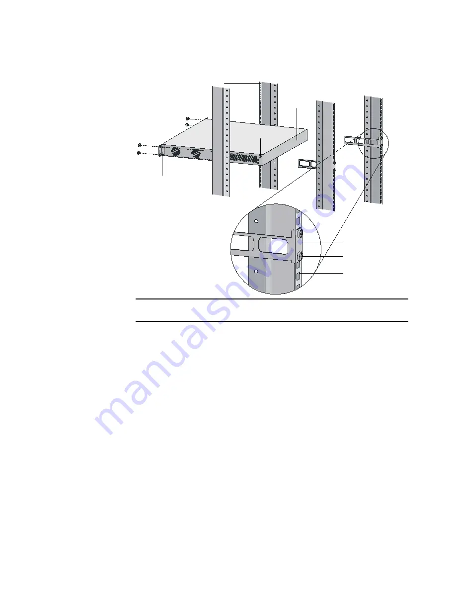
Figure 24
Fix front and rear mounting ears
After the switch is pushed into the cabinet, ensure that the upper edge of rear
mounting ears is tightly contacted with the load-bearing screw, as shown in
Figure 25.
Screw 1: Used to bear the weight
Screw 2: Used to fix rear mounting ears to rear brackets
Screw 1
Screw 2
Rear mounting ear
Front mounting ear
Front square-holed bracket
Rear panel
Rear square-holed bracket
Summary of Contents for 4800G Series
Page 28: ...28 CHAPTER 2 PREPARATING TO INSTALL THE SWITCH...
Page 52: ...52 CHAPTER 3 INSTALLING THE SWITCH...
Page 64: ...64 CHAPTER 5 LOADING THE BOOT ROM AND HOST SOFTWARE Figure 60 Properties dialog box...
Page 72: ...72 CHAPTER 5 LOADING THE BOOT ROM AND HOST SOFTWARE...
Page 78: ...78 CHAPTER A LIGHTNING PROTECTION FOR THE SWITCH...


