62
C
HAPTER
4: I
NSTALLING
THE
R
OUTER
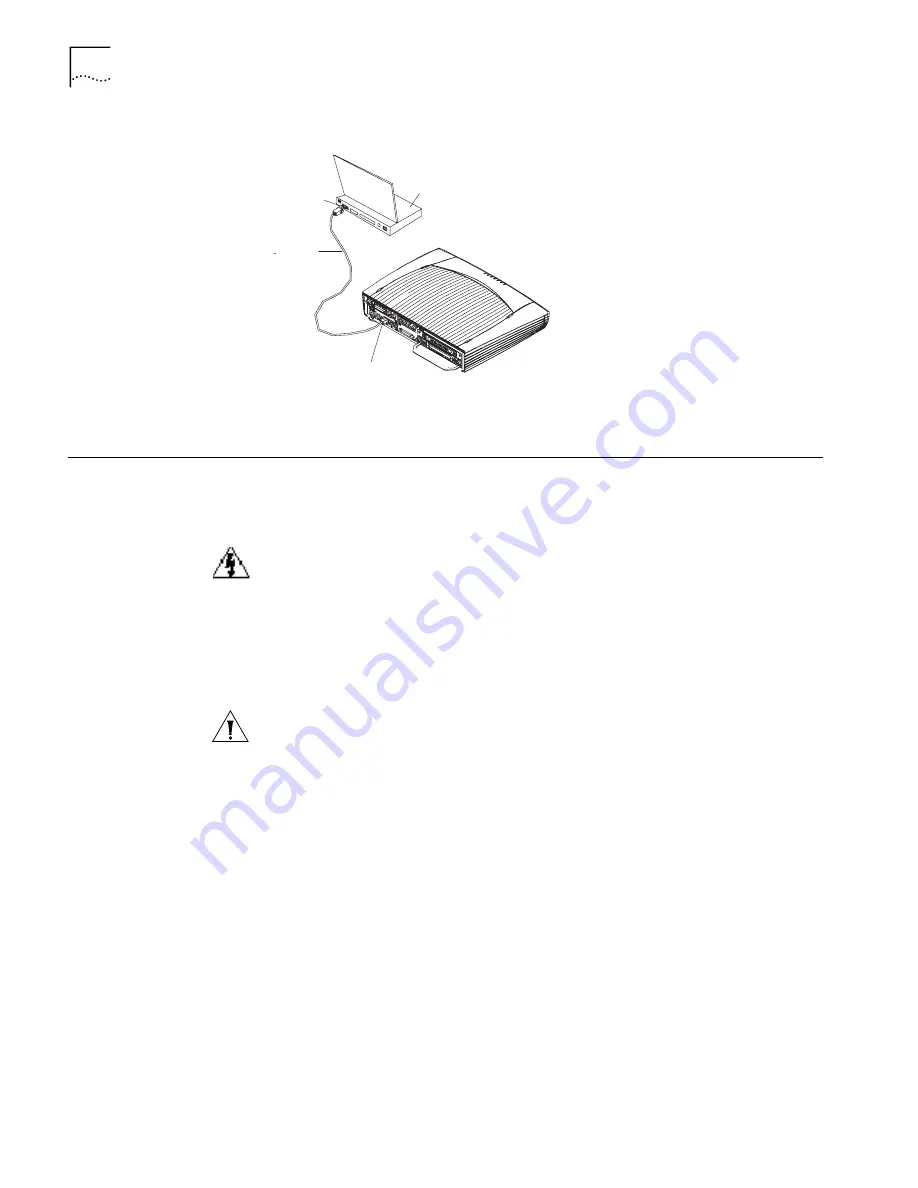
Figure 64
Connecting the Console Port to the PC (router shown for illustration only)
After connection, power on the router. The startup information of the router is
displayed on the console terminal.
Installing SICs and
MIMs
Before you install a SIC or MIM, assemble the following equipment:
■
Flat-blade screwdriver
■
Anti-static wrist strap
The Router 5000 Family routers do not support hot swappable SICs and MIMs. To
avoid injury from electric shock or damage to a router, put on an anti-static wrist
strap, make sure that power to the router has been turned off and that the power
cord has been unplugged before performing any of the following operations.
Before you can install a SIC or MIM, you must remove the filler panel from the slot.
Remove the captive screws of the blank filler panel by unscrewing them in a
counter-clockwise direction with the flat-blade screwdriver, as shown below.
Do not remove the blank filler panel with black film above SLOT0.
To install a SIC or MIM:
1
Turn the router so the rear panel faces you.
2
Turn off the power switch of the router and unplug the power cord.
3
Match the remote edge of the module with the slot on the router's rear panel.
4
Push the module into the router until its front panel is level with the back panel of
the router.
5
Fasten the module into the router with the captive screws.
6
Power on the router, and check the LED of the corresponding slot on the front
panel. After the initialization of the module, if the LED for the corresponding slot is
on, the module is operating normally. If the LED for the corresponding slot remains
off, the POST for the module has failed and you should contact your Service
representative.
Console
cable
PC
PC serial
interface
Console port
Summary of Contents for 3C13701
Page 14: ...12 CHAPTER 1 INTRODUCING THE ROUTER 5000 FAMILY ...
Page 34: ...32 CHAPTER 2 INTRODUCING ROUTER 5012 SICS ...
Page 57: ...ADSL MIMM 55 ...
Page 58: ...56 CHAPTER 3 INTRODUCING ROUTER 5000 FAMILY MIMS ...
Page 68: ...66 CHAPTER 4 INSTALLING THE ROUTER ...
Page 90: ...88 CHAPTER 7 TROUBLESHOOTING ...
Page 100: ...98 APPENDIX A CABLE SPECIFICATIONS ...
Page 104: ...102 APPENDIX A OBTAINING SUPPORT FOR YOUR PRODUCT ...


