background image

2N TELEKOMUNIKACE a.s., www.2n.cz

70/82

4.1 Cabin Switch Connection

The Cabin Switch unit helps you connect up to 4 IP devices located in the lift cabin. It 

transfers data from the DSL line to 4 Ethernet ports, which support the rate of 10 or 

100  Mbps.  Two  ports  provide  PoE  802.3af  Class  2  (6.49  max)  and  allow  up  to  2 

devices without power supply to be connected. Typically, they include an emergency 

communicator, an IP camera and an access system reader.

It is interconnected with the 

 main unit and communicates with it using a 

2N  LiftGate

®

 carried in a towrope from the lift cabin to the machine room.

2-wire cable

The Cabin switch unit is intended for lift cabin installation and suspended using screws 

or mounted on a DIN rail. There is a DIN rail mounting profile with a lock on the cabin 

unit  back  side.  Put  the  upper  profile  side  on  the  DIN  rail  and  push  the  cabin  unit 

bottom to fit and lock the cabin unit to the DIN rail. To release the cabin unit from the 

DIN  rail,  pull  the  DIN  rail  lock  a  little,  using  a  screwdriver,  for  example.  Now  remove 

the cabin unit from the DIN rail.

1 or 2 48 V power supplies (marked as 1xPS or 2xPS) are available on the main unit for 

feeding the cabin unit, depending on the device version. Each power supply is able to 

feed 1 or 2 cabin units, i.e. the total of up to 4 units in the two-supply version. Each 

cabin  unit  can  be  installed  in  a  different  lift  cabin.  The  power  supply  is  short  circuit 

resistant and has a resettable electronic fuse.

Warning

As  power  supplies  warm  up  during  operation,  it  is  necessary  to  install 
the  device  in  such  a  manner  that  air  can  flow  from  the  fan  to  the 
ventilating holes on the other side of the device.

Summary of Contents for LiftGate

Page 1: ...www 2n cz 2N LiftGate LTE Router User Manual Firmware Initial version Version 1 0 ...

Page 2: ...marks and or trademarks or brands protected by law 2N TELEKOMUNIKACE a s administers the FAQ database to help you quickly find information and to answer your questions about 2N products and services On www faq 2n cz you can find information regarding products adjustment and instructions for optimum use and procedures What to do if 2N TELEKOMUNIKACE a s hereby declares that the 2N product complies ...

Page 3: ...ficate All development production and distribution processes of the company are managed by this standard and guarantee a high quality technical level and professional aspect of all our products The 2N is the holder of the Type certificate of the TÜV SÜD Czech company ...

Page 4: ...onents and Associated Products 1 3 Terms and Symbols Used 2 Device Installation 2 1 Before You Start 2 2 Mechanical Installation 2 3 Electric Installation 2 4 Overview of Connectors 2 5 Overview of LED Indicators 2 6 RESET Button Function 2 7 Retrieval of 2N LiftGate in Network by 2N Network Scanner ...

Page 5: ...Firewall 3 2 7 Port Forwarding 3 2 8 Events 3 2 9 Commands 3 2 10 Power Supply and Battery 3 2 11 Input and Output Pins 3 2 12 Access 3 2 13 Time 3 2 14 Log 3 3 Maintenance Configuration 3 3 1 Restart 3 3 2 Firmware 3 3 3 Battery Installation 3 3 4 Log 4 Function and Use 4 1 Cabin Switch Connection 4 2 Supported Devices 4 3 Maintenance 5 Technical Parameters 6 Supplementary Information 6 1 Trouble...

Page 6: ...ce the product outline its application options 2N LiftGate and highlight the advantages following from its use The section also includes safety precautions Here is what you can find in this section 1 1 Product Description 1 2 Components and Associated Products 1 3 Terms and Symbols Used ...

Page 7: ...ine room to the lift cabin including the backed up power supply This LTE router communicates with the outer world via an LTE or WAN port Basic Features 2 wire data transmission Web interface based configuration Multimedia communication Remote management via 2N Elevator Center automatic configuration bulk update remote access real time monitoring Internal backup battery pack Compliance with latest ...

Page 8: ...2N TELEKOMUNIKACE a s www 2n cz 8 82 System Schema Example of Cabin Switch and Third Party Equipment Wiring Diagram 2N LiftGate ...

Page 9: ...LiftGate Main Unit supports 2 CS Accu EU plug main unit support for 2 Cabin switch units Part No 5024201E 2N LiftGate Main Unit 4 CS supports Accu EU plug main unit support for 4 Cabin switch units Part No 5024101US 2N LiftGate Main Unit 2 CS supports Accu US plug main unit support for 2 Cabin switch units ...

Page 10: ...4 CS supports Accu US plug main unit support for 4 Cabin switch units Part No 5024101AU 2N LiftGate Main Unit 2 CS supports Accu AU plug main unit support for 2 Cabin switch units Part No 5024201AU 2N LiftGate Main Unit 4 CS supports Accu AU plug main unit support for 4 Cabin switch units ...

Page 11: ...tch 4x ETH 12 V DC cabin unit for connection of up to 4 devices in the lift cabin Part No 22041572 GSM UMTS LTE 2N Antenna SMA connector 3m cable for signal quality improvement Management Services Part No 9137991 2N Elevator Center device fee Cloud service license for lift bulk management ...

Page 12: ...iated Devices Part No 920640 2N LiftIP cabin audio unit Basic model EN provides automatic dialing of up to six numbers Part No 920640X 2N LiftIP cabin audio unit cable version like 920640 contains LED microphone and speaker connected via cables ...

Page 13: ...e by this information to prevent persons from injury Warning Always abide by this information to prevent damage to the device Caution Important information for system functionality Tip Useful information for quick and efficient functionality Note Routines or advice for efficient use of the device The following symbols are used on the main unit ...

Page 14: ...ical accident hazard This warning relates to the main unit high voltage AC input Caution High energy from input Disconnect all power supplies The main unit includes multiple inputs all of which have to be disconnected before service intervention ...

Page 15: ... and its installation 2N LiftGate Here is what you can find in this section 2 1 Before You Start 2 2 Mechanical Installation 2 3 Electric Installation 2 4 Overview of Connectors 2 5 Overview of LED Indicators 2 6 RESET Button Function 2 7 Retrieval of 2N LiftGate in Network by 2N Network Scanner ...

Page 16: ...e signal strength check the LED indicator 2N LiftGate status or display the information via the device web interface For the allowed range of operating temperatures refer to Section 5 Technical Parameters 2N LiftGate may not be operated on sites exposed to direct solar radiation or near heat sources 2N LiftGate is designed for indoor applications It may not be exposed to rain flowing water condens...

Page 17: ...he antenna near television 2N LiftGate broadcasting or other high frequency sensitive devices may have an adverse affect on their functionalities Caution Make sure that you have all requisites for putting in 2N LiftGate operation SIM card LAN PC interconnecting cable ...

Page 18: ...it is installed on an easily accessible place the Internet access or SIM cards can be misused Mount the main unit on a wall using the provided dowels and screws We 2N LiftGate recommend that the main unit should be installed in a maximum height of 2 meters Drill 2 holes spaced apart 176 mm 6 9 inches and insert the dowels Put the screws through the device box metal profile holes and tighten them i...

Page 19: ...2N TELEKOMUNIKACE a s www 2n cz 19 82 ...

Page 20: ...rected upwards on the right hand side Interconnect the fitted battery pack with the motherboard using a Faston cable respecting the required polarity Caution Maintain the battery pack polarity In the case of the battery polarity reversal is protected 2N LiftGate with a relay to be hazard free Replace the upper cover to the main unit and tighten the fixing screws Make sure that the grounding wire i...

Page 21: ... a battery pack in the main unit if you suspect any electrical or mechanical damage Never use without the protective cover to avoid electric 2N LiftGate shock hazard wrong functionality due to misconnection and last but not least damage or destruction of the electronics as a result 2N LiftGate of an electric short circuit or adverse environmental effects Without the cover is not protected against ...

Page 22: ...ts LAN 1 3 LAN connector 10 100 1000BaseT RJ 45 Ca5 or higher recommended LAN1 provides PoE 802 3af Class 2 6 45 W max WAN WAN connector 10 100 1000BaseT RJ 45 Ca5 or higher recommended DIV Optional LTE antenna with an SMA connector for a better signal quality MAIN Main LTE antenna with an SMA connector SIM 1 2 SIM card slots The use of SIM 2 is optional PIN secured SIM cards can be inserted Make ...

Page 23: ...2N TELEKOMUNIKACE a s www 2n cz 23 82 ...

Page 24: ...ically e g provider service failure Red slow flashing permanent error admin intervention is required e g via the device web interface Red fast flashing HW error on site service intervention is required e g DSL short circuit battery error defect POWER Indicates the general power supply status Blue external supply is progress battery is kept charged Blue short flashing external supply in progress lo...

Page 25: ...Internet connection available The LED color signals the network technology used Yellow 2G Green 3G Blue 4G Slow network LED flashing indicates that the SIM card and registration are OK but the Internet connection is unavailable Red slow flashing SIM OK network search in progress Red fast flashing SIM error PIN unset or card rejected by network No light indication SIM not inserted SIGNAL STRENGTH I...

Page 26: ... connection is disabled in configuration MOBILE DATA and LEDs combined indicate the general Internet WAN status Permanently on active primary connection Slow flashing active backup connection Fast flashing Internet connection unavailable CABIN SWITCH 1 2 Indicates the states of connected cabin switches 1 2 Blue voltage OK connected Blue slow flashing disconnected no consumption Red voltage warning...

Page 27: ...cuit No light signaling the cabin switch is unavailable the device is supported by 2 cabin switches only NOTE device version with 2 cabin switch support 2xCS on positions 1 and 2 The 4 cabin switch support device version 4xCS supports all the 4 positions Flashing Frequencies Slow flashing Flashes 1 1 interval 1 s 0 5 s light on ON 0 5 s no light OFF Fast flashing Flashes 1 1 interval 0 2 s 0 1 s l...

Page 28: ... button 5 times to reset the factory defaults the device will be restarted after the factory reset Restart Press and hold the RESET button for approx 4 s until all the LEDs go off and the left LED starts shining blue The main unit system will be restarted if powered from the mains or turned off if a battery supply is used Note The beginning of the factory default reset restart is signaled by all t...

Page 29: ...work Scanner Description The application helps find the IP addresses of all devices in the LAN 2N LiftGate Download the application from the 2N web sites Make sure that www 2n cz Microsoft NET Framework 2 0 has been installed before installation Run the installer 2N Network Scanner Use the Setup Wizard for successful installation Setup Wizard of 2N Network Scanner Having installed start the applic...

Page 30: ... web interface login Browse 2N LiftGate window for configuration To change the device IP address select and Config enter the required static IP address or activate DHCP Remember to confirm the setting change with a password If the default password has been changed upon web interface login use the current password otherwise the default password is If the found device is grey highlighted its IP addr...

Page 31: ...equested upon the main unit factory default reset A new password will be requested for the next login There are 3 tabs on the left side of the home page upper bar The State tab shows basic information on the main unit device ID time data Configuration helps set the main unit according to the user requirements Maintenance is used for configuration and firmware maintenance helps back up and refresh ...

Page 32: ...ud service for the main unit 2N Elevator Center remote management Contact your distributor for the service access data Refer to for more details on www 2n cz 2N Elevator Center 3 1 State Basic Information 3 2 Configuration Cellular 3 3 Maintenance Configuration ...

Page 33: ...Basic Information The State Basic Information tab displays the main unit ID and time and is also used as a home page for web interface login 2N LiftGate 3 1 1 Mobile Network 3 1 2 Networking 3 1 3 Power Supply and Battery 3 1 4 Input and Output Pins ...

Page 34: ...currently used SIM card IMEI LTE module serial number Network status provider network connection status Network name network provider s name Network technology network technology used Network data network data status MCC MNC country and network codes Network signal current signal strength BTS LAC group BTS cell group number in the network BTS cell ID unique cell ID ...

Page 35: ...pt count count of the remaining PIN code attempts IMSI unique international SIM card code ICCD SIM card production number 3 1 2 Networking The Networking tab shows the status of data routing to the Internet Active routing the currently used routing to the Internet Primary direction preferred direction to the Internet Mobile network WAN ...

Page 36: ...loss function setting status Mobile network shows the mobile network routing parameters IP IP address assigned from the mobile network Mask IP address mask assigned from the mobile network Gateway default gateway assigned from the mobile network DNS1 primary DNS server address assigned or as configured DNS2 backup DNS server address assigned or as configured WAN shows the WAN routing parameters MA...

Page 37: ...mary DNS server address assigned or as configured DNS 2 backup DNS server address assigned or as configured LAN shows the LAN parameters MAC LAN port HW address factory setting IP LAN IP address as configured Mask LAN mask as configured DHCP clients shows the LAN devices that requested IP addresses from the DHCP server IP IP address assigned from the range configured MAC device HW address Validity...

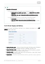
Page 38: ... Up connected or Down disconnected Rate data rate 10 100 1000 Mbps Mode port mode 3 1 3 Power Supply and Battery The Power Supply and Battery tab provides information on the general power supply state Active power source currently used power supply External external power supply 230 24 V Battery 12 V battery supply External voltage current voltage current from an external power source 24 V ...

Page 39: ...s battery detection and charging statuses Battery voltage current battery voltage typically 13 6 V battery current for charging for discharging Battery capacity life time battery nominal capacity 9 or 18 Ah number of days after battery installation Usable capacity Charge level usable battery capacity battery charging level in Charger temperature charging chip temperature up to 120 C Battery temper...

Page 40: ...ax recommended up to 0 7 A 3 1 4 Input and Output Pins The Input Output Pins tab shows the states of the device logic inputs and outputs Input 1 0 means that the input is not occupied voltage below 2 V 1 means that IN1 is occupied voltage over 4 V Input 2 0 means that the input is not occupied voltage below 2 V 1 means that IN2 is occupied voltage over 4 V Output 1 0 means that the relay is open c...

Page 41: ...e applied immediately Mode select the active priority SIM card or an unprioritized SIM card Caution In the case of a signal data connection loss of the active SIM card the backup SIM card is switched on in the last 3 possible modes In the case of a signal data connection loss and switch over from the priority SIM to the backup SIM card in the priority modes an attempt is made every hour to return ...

Page 42: ...ter the network number for the main unit to log in if you leave it empty a network will be selected automatically Network technology select the network technology technologies to you can log in Note If a combination of network technologies is selected the fastest available network is always chosen LTE 4G network of 4th generation UMTS 3G network of 3rd generation GSM 2G network of 2nd generation 3...

Page 43: ...2 3 WAN 3 2 4 LAN 3 2 5 VPN 3 2 6 Firewall 3 2 7 Port Forwarding 3 2 8 Events 3 2 9 Commands 3 2 10 Power Supply and Battery 3 2 11 Input and Output Pins 3 2 12 Access 3 2 13 Time 3 2 14 Log 3 2 1 Routing The Routing tab shows the parameters of data routing to the Internet ...

Page 44: ...unctional non functional Restart after connection loss allow for a preventive system restart if the functional Internet connection has been lost Restart delay set the Internet connection loss time in minutes after which the system is restarted if allowed so Caution If both directions i e both primary and backup are set in the routing mode the PING queries are sent to both of them which checks thei...

Page 45: ...ss Point APN APN as defined by the network provider for Internet connection not requested in some networks Username user name as defined by the provider for Internet login not requested in some networks Password password as defined by the provider for Internet login not requested in some networks DNS from mobile network allowed use of the DNS IP address obtained from ...

Page 46: ...s the Internet connection parameters via an Ethernet port DHCP enable the assignment of basic network parameters by the DHCP server IP address mask gateway IP main unit IP address if not allowed by DHCP Mask network IP mask if not allowed by DHCP Gateway gateway IP address if not allowed by DHCP DNS from DHCP enable the use of the DNS IP address obtained from the DHCP server DNS 1 primary DNS serv...

Page 47: ...vices connected to LAN ports or DSL lines IP lease time time in minutes of assignment of network parameters to devices First DHCP IP IP address defining the area of addresses assigned to devices Last DHCP IP IP address of the end of the area from to interval DNS masquerade allow the devices to be assigned the system IP address IP parameter as the DNS server address the DNS queries will be automati...

Page 48: ...ble update All the currently connected devices that have been assigned an address by the DHCP server will be uploaded MAC device HW address defined by the manufacturer IP IP address to be assigned to a device by the DHCP server 3 2 5 VPN The VPN tab provides parameters for the creation of a selected VPN Virtual Private Network connection Enable OpenVPN allow this function to create a third directi...

Page 49: ...ined from the VPN server administrator client crt device certificate generated for each device 2N LiftGate client key private device key generated for each device 2N LiftGate ta key tls authority key obtained from the VPN server administrator SELECT FILE for permanent storing of certificates in the device memory UPLOAD upload selected files certificates and keys to the device 3 2 6 Firewall The Fi...

Page 50: ...om the Internet Protocol TCP or UDP Port port number 0 to 65535 Interface for selected connection MN WAN LAN VPN or any Source IP for a remote device with this address or with any address if the parameter is empty Description user definable field for a connection ADD NEW add a new connection Caution If the firewall is active and access should be allowed to the device web interface from the selecte...

Page 51: ...ort forwarding description 3 2 8 Events The Events tab helps you set sending of information SMS or HTTP commands for events that occurred 2N LiftGate allows you to send messages on events occurred on a device either via SMS by completing the phone number to which the information is to be sent or using HTTP commands by completing the HTTP URL address In case no event parameters have been selected n...

Page 52: ...tional with at the beginning SMS text SMS text definition Can include Unicode characters and inserted parameters character and a letter Parameters for SMS and HTTP Destinations i inserts the Identification parameter s inserts the serial number 2N LiftGate i inserts a text defined for each event type i inserts event date and time m inserts an internal message for some events only inserts the charac...

Page 53: ... a valid URL of the target server followed optionally by a text in combination with inserted parameters character and a letter like in SMS compiled as awaited by the server You can enable SMS HTTP command sending for each type of event separately You can set a text for each type of event to be inserted in the SMS or HTTP command A delay in seconds can be set for some types of events defining the m...

Page 54: ...details Input 1 high after input 1 activation Input 1 low after input 1 deactivation Input 2 high after input 2 activation Input 2 low after input 2 deactivation Connection lost loss of the Internet connection SMS is sent instantaneously HTT command will not be sent until the connection is recovered to inform the server of the connection loss time Switched to primary direction switch to the primar...

Page 55: ...ther HW errors m inserts a text describing the error 3 2 9 Commands In the Commands tab you can enable the reception of commands sent in SMS to 2N LiftGate Allow from HTTP API enable the reception of commands via HTTP API no more restrictions Description user definable field for a SMS command enable description Phone number sender s number local or international with at the beginning Password at S...

Page 56: ...ck an SMS with identification data cfg default resets configuration defaults cfg apn1 apn name pass sets the APN parameters user name and password in the Configuration Mobile Data SIM 1 section apn is mandatory name a pass may be empty cfg apn2 apn name pass sets the APN parameters user name and password in the Configuration Mobile Data SIM 2 section apn is mandatory name a pass may be empty out i...

Page 57: ... mobile cz LiftGate setting 3 2 10 Power Supply and Battery The Power Supply and Battery tab helps you complete information on the 2N battery pack state LiftGate timeout in days following the battery pack installation Battery life time alert after which the battery expiration warning command should be sent number of days after which the battery expiration Repeat life time alert warning should be r...

Page 58: ...informs of the pin states and settings protective period in tenths of a second during which the pin Input 1 2 delay state change should last until the change is detected on the input pin Note The input activation generates an event Input X high The input deactivation generates an event Input X low ...

Page 59: ...t otherwise the required state holds as set in the Duration parameter and then switches back In case the Event parameter is set to a valid value the output closes opens whenever the set event occurs The output states can also be controlled using SMS or HTTP commands initial output state at system power up Output 1 2 start state ON state duration in tenths of a second Output 1 2 ON duration OFF sta...

Page 60: ...gout time idle time in minutes after which the user is automatically logged out administrator Admin password with all rights Current password new password New password new password confirmation Confirm new password CHANGE PASSWORD confirm and save the new password Guest password with limited rights The guest has only access to the State tab and no access to the Maintenance Configuration tab ...

Page 61: ...self signed certificate is used 3 2 13 Time The Time tab helps you set the exact time to be used in 2N LiftGate Time and date are always set automatically from the mobile network a few seconds after the system startup the time of the first system log records is thus 0 00 and the date is Jan 1 Only if no SIM card is inserted or no mobile network signal is available the NTP server has to be used If ...

Page 62: ...le NTP server 1 domain or IP address NTP server 1 NTP server 2 domain or IP address NTP server 2 NTP server 3 domain or IP address NTP server 3 3 2 14 Log The Log tab is used for logging various events or errors during operation of 2N LiftGate IP address of the server to used for completing the Remote syslog server which SYSLOG records are to be sent ...

Page 63: ...ice parameters to their default values Download configuration download the device configuration in the JSON format and save it to a file Upload configuration upload configuration in the JSON format from a selected system to the device Force the device restart to apply the uploaded configuration Caution The configuration file does not include the Configuration Access login date Factory reset reset ...

Page 64: ... tab is used for forcing the restart 2N LiftGate CONFIRM RESTART an immediate system restart is performed Caution Should the main unit system be turned off or restarted unintentionally including simultaneous disconnection of external and battery supplies e g the system log will not be saved properly and this may result in a file damage or loss 3 3 2 Firmware The Firmware tab is used for the firmwa...

Page 65: ...K NEW VERSION check the availability of the latest FW version on the update server DOWNLOAD AND UPDATE download and update the latest available FW version to the device Select firmware file download and update FW from a local file UPDATE FROM FILE send the local file with the new FW to the device and update 3 3 3 Battery Installation The Battery Installation tab shows information on the battery pa...

Page 66: ... installed battery parameters are not part of the system configuration and thus are not changed during the factory default reset 3 3 4 Log The Log tab shows records on the system start and all important events or errors helps detect operational problems and provides firmware troubleshooting support to the service department DOWNLOAD download the log content to a file REFRESH refresh the log displa...

Page 67: ...2N TELEKOMUNIKACE a s www 2n cz 67 82 SET display the log to be filtered CLEAR delete the set filter and show the complete log content ...

Page 68: ... common routers by its ability to operate from a 2N LiftGate backup battery during power outages The Ethernet ports on the main unit support the rate of 10 100 1000 Mbps and are marked as LAN1 LAN2 and LAN3 48 V PoE supply is available on port LAN1 for feeding a connected device IP intercom or IP camera e g The DSL line is a two wire interface for Cabin switch connection It combines 48 V supply an...

Page 69: ...port for 4 Cabin switch units The aggregate working load that meets the condition of 60 15 minutes of operation call is 55 W The aggregate working load that meets the condition of 4 hours of operation is 15 W 2N LiftGate 5024201xx 18 Ah battery pack support for 4 Cabin switch units The aggregate working load that meets the condition of 60 15 minutes of operation call is 110 W The aggregate working...

Page 70: ... is a DIN rail mounting profile with a lock on the cabin unit back side Put the upper profile side on the DIN rail and push the cabin unit bottom to fit and lock the cabin unit to the DIN rail To release the cabin unit from the DIN rail pull the DIN rail lock a little using a screwdriver for example Now remove the cabin unit from the DIN rail 1 or 2 48 V power supplies marked as 1xPS or 2xPS are a...

Page 71: ...Supported Devices To ensure emergency communication in the lift we recommend that 2N LiftGate should be interconnected with the communicator For lift cabin video 2N LiftIP surveillance we recommend that you use the IP camera model Axis P9106 E ...

Page 72: ... the old battery out and replace it with a new one Interconnect the battery with the motherboard using the FASTON cable and reconnect the mains supply Replace the upper cover and tighten the cover fitting screws Make sure that the grounding wire is connected with the cover while replacing the cover Confirm the new battery installation and complete the installation date in the Maintenance Battery I...

Page 73: ...with the main unit on and the protective cover removed unless you are a properly trained person with a higher qualification and educated according to Regulation 50 1978 Coll Never install a damaged battery pack Never insert a battery pack in the main unit if you suspect any electrical or mechanical damage Never use without the protective cover to avoid electric 2N LiftGate shock hazard wrong funct...

Page 74: ...r interface Control web interface Default ID Password admin 2n Device State Indicator refer to 2 5 Overview of LED Indicators Antenna Impedance 50 Ω 2x SMA connector for main optional antenna I O module DSL 48 V 1 A version with support for 2 Cabin switches Cabin switch 1 2 48 V 1 A version with support for 4 Cabin switches Cabin switch 3 4 INP pin1 10 5 V 5 mA pin2 input 1 47 kOhm serial resistor...

Page 75: ...V 6 5 W max Class2 Frequency bands EU version LTE FDD B1 B3 B5 B7 B8 B20 LTE TDD B38 B40 B41 WCDMA B1 B5 B8 GSM B3 B AU version LTE FDD B1 B2 B3 B4 B5 B7 B8 B28 LTE TDD B40 WCDMA B1 B2 B5 B8 GSM B2 B3 B5 B8 US version LTE FDD B2 B4 B12 WCDMA B2 B4 B5 Interface refer to 2 4 Overview of Connectors Weight 2 2 kg without battery pack 4 7 kg with battery pack Dimensions 270 x 240 x80 mm IP cover IP20 O...

Page 76: ...max DSL for connection with the main unit 4x LAN for connection of 4 IP devices of any type first 2 positions provide PoE 10 100BaseT LAN1 2 PoE RJ 45 Ca5e or higher recommended I O OUT 12 V DC 100 mA 1 2 W DSL 19 W max consumption own consumption OUT port 4W 15 W max from PoE LAN 1 2 LAN PoE 48 V 7 5 W port 15 W aggregate Operating temperature 20 C to 50 C ...

Page 77: ...77 82 6 Supplementary Information This section describes supplementary information on the product Here is what you can find in this section 6 1 Troubleshooting 6 2 Directives Laws and Regulations 6 3 General Instructions and Cautions ...

Page 78: ...e power supply and battery status Guest user name access is unavailable Set the access first on the Configuration Access tab Local time and UTC in the device configuration shows 1 2 1980 Enable NTP on the Configuration Time tab Check the Internet access For the most frequently asked questions refer to faq 2n cz ...

Page 79: ... 35 EU for electrical equipment designed for use within certain voltage limits 2014 30 EU for electromagnetic compatibility 2014 33 EU for lifts and safety components for lifts 2011 65 EU on the restriction of the use of certain hazardous substances in electrical and electronic equipment 2012 19 EU on waste electrical and electronic equipment ...

Page 80: ...on of the product caused by incompetent replacement of parts or due to the use of reproduction parts or components The manufacturer shall not be liable and responsible for any loss or damage incurred as a result of a natural disaster or any other unfavourable natural condition The manufacturer shall not be held liable for any damage of the product arising during the shipping thereof The manufactur...

Page 81: ...ic Waste and Used Battery Pack Handling Do not place used electric devices and battery packs into municipal waste containers An undue disposal thereof might impair the environment Deliver your expired electric appliances and battery packs removed from them to dedicated dumpsites or containers or give them back to the dealer or manufacturer for environmental friendly disposal The dealer or manufact...

Page 82: ...2N TELEKOMUNIKACE a s www 2n cz 82 82 2N TELEKOMUNIKACE a s Modřanská 621 143 01 Prague 4 Czech Republic Phone 420 261 301 500 Fax 420 261 301 599 E mail sales 2n cz Web www 2n cz v1 0 ...

Reviews: