background image

2

©2013 2GIG Technologies Inc. All Rights Reserved.

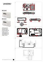
SELECTING A LOCATION FOR THE KEYPAD

1

Make


sure


that


AC


Power


is


available


nearby.

TIP: 

Be


careful


of


studs,


electrical


wires


and


pipes


in


the


wall.

2

Use


the


keypad’s


back


cover


as


a


template


to


mark


the


screw


holes


with


a


pencil


and


the


power


(wiring)


access


hole.

3

Use


a


drywall


saw


to


cut


the


wiring


hole.

Mounting the Keypad

1

Use


the


3


screws


and


anchors


that


are


supplied


to


attach


the


mounting


plate


to


the


wall.

2

Route


18


AWG


wire


between


the


keypad


and


the


location


of


the


power


supply.

Wire Size and Length

To


ensure


proper


operation,


Do


Not


exceed


the


following


maximum


length


for


the


wire


size


installed:

To


ensure


that


the


appropriate


wire


size


and


length


are


installed,


measure


the


voltage


between


the


power


connection


terminals


at


the


back


of


the


control


panel.


The


voltage


measured


must


not


fall


below


11


volts


DC


or


nuisance


“AC


Power


Loss”


messages


may


be


displayed


and


reported.

NOTE: 

In


the


United


States,


wiring


routed


inside


walls,


ceilings,


and


floors


must


comply


with


requirements


of


the


National


Electrical


Code,


ANSI/NFPA


70


and


local


building


codes.


For


wiring


from


the


output


of


the


2GIG


class


II


power


supply,


wiring


rated


CL2,


CL2X,


CL2R,


or


PLTC


is


recommended


to


satisfy


these


requirements.


If


this


wiring


is


installed


in


an


air


plenum


(space


used


for


environmental


air


exchange)


it


must


be


rated


CL2P


(plenum


rated).

Connect the Power Wires to the Keypad

1

Re

connect


the


hanging


strap.

2

Use


#6


insulated


spade


terminals


(not


supplied)


to


connect


wires


from


the


power


supply


to


the


keypad.

3

Close


the


keypad.

4

Connect


the


power


wires


to


the


power


supply.

Wire Size

Maximum Length

22


AWG

55


feet


(16.8


meters)

20


AWG

85


feet


(25.9


meters

22


AWG


2

pairs

(19


AWG


equivalent)

110


feet


(33.5


meters)

18


AWG

135


feet


(41.1


meters)

A

Snap case closed.

B

Tighten case screw.

A

Left Terminal 14 VDC(+)

B

Right Terminal 14 VDC (-)

C

18 AWG/2-Conductor

Summary of Contents for Touch Screen Wireless Keypad

Page 1: ...d but also extends all user control of the 2GIG Control panel to other locations in a user s home Using the TS1 users can control lights thermostat and door locks and see the status of every zone in their home using the exact same and familiar interface found on the Control Panel The keypad is designed for indoor use only IMPORTANT Not for UL 985 installations The panel and buttons serve as contro...

Page 2: ... must not fall below 11 volts DC or nuisance AC Power Loss messages may be displayed and reported NOTE In the United States wiring routed inside walls ceilings and floors must comply with requirements of the National Electrical Code ANSI NFPA 70 and local building codes For wiring from the output of the 2GIG class II power supply wiring rated CL2 CL2X CL2R or PLTC is recommended to satisfy these r...

Page 3: ... Go To button 6 To go to question 4 enter 04 7 Select the RF Keypad number to assign to the TS1 Use the arrow to select the RF Keypad number 1 4 After selecting the RF Keypad number press the arrow to start configuring the specific parameters for the RF Keypad 8 Press the arrow or press the number 1 on the keypad toggle the se ng on the first ques on to used Press the arrow to con nue configuring ...

Page 4: ...ING THE TS1 To remove a TS1 from a Control Panel s configuration do the following 1 From the Control Panel go to Installer Toolbox System Configuration 2 Select the Go To button and enter 04 The Control Panel displays Q4 select RF keypad 1 to 4 Select the configured TS1 you wish to remove and press the arrow 3 Mark the RF Keypad number selected as unused by pressing the arrow This action toggles t...

Page 5: ...t This certification means that the equipment meets certain telecommunications network protective operational and safety requirements The Department does not guarantee the equipment will operate to the user s satisfaction Before installing this equipment users should ensure that it is permissible to be connected to the facilities of the local telecommunications company The equipment must also be i...

Reviews: