Copyright © 2015 Nortek Security & Control
3
USING THE 2GIG EASY UPDATER FOR GC2
Control Panel Firmware Update Instructions
Make sure that the 2GIG-UPDV has the latest control panel and Touchscreen
Keypad
fi
rmware loaded. See sec on "How to Update Easy Updater for GC2" and
update if necessary.
The 2GIG-UPDV was preloaded at the me of produc on with product
fi
rmware.
On the back of the device it shows the factory loaded product
fi
rmware revision
and the serial number for the 2GIG-Easy Updater for GC2
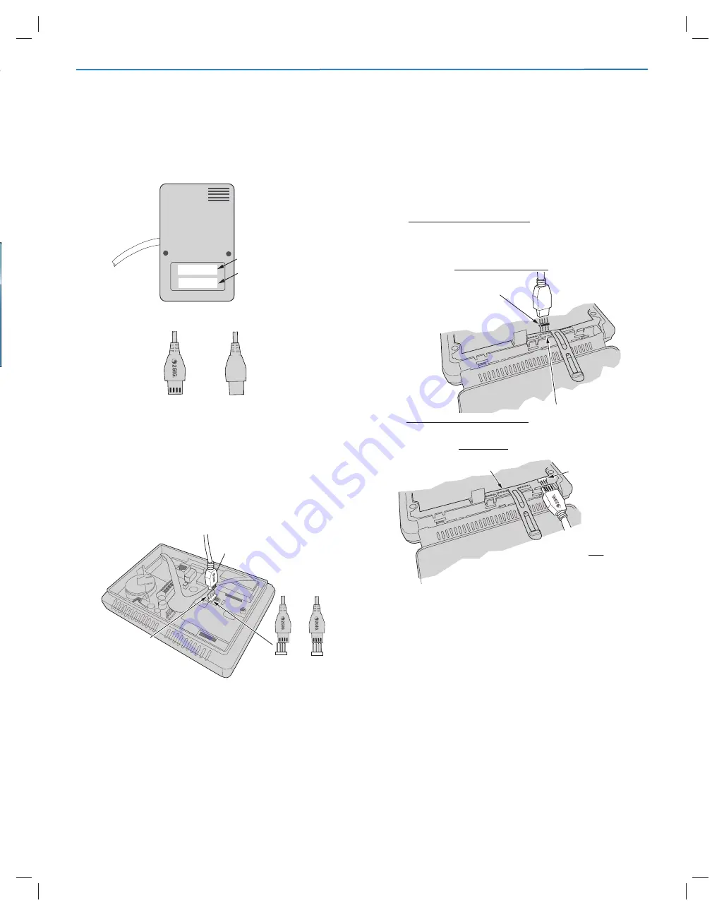
Figure 16.
Serial Number/Firmware Pre-Load Labels on Backside of Updater
Figure 17.
Reference Diagram of Pigtails/ Slots & Logo side & Non-Slo ed Side
Update the Control Panel
To update the Control Panel
fi
rmware:
1. Remove the backplate from the Control Panel. For instruc ons, see the
Go!Control Panel’s Installa on & Programming Guide.
2. Disconnect power and ba ery.
3. Plug the device’s pigtail cable into the Control Panel’s J4 Pin Connector port
as shown in Figure 18.
4. Plug in the back-up ba ery.
5. Power ON the Control Panel
Figure 18.
Firmware Update Cable and J4 Pin Connector Port
Firmware Update
The UPDV Device will communicate with the Control Panel. The UPDV Device
will determine that a
fi
rmware update can occur and wait for the start bu on to
be pressed:
L13 12084
(Control Panel or TS1 version build number scrolling)
update in progress:
F O
(display % progress (0 to 100), scrolling decimal points
when communica ng with panel).
Press the Start Bu on.
NOTE:
Intermediate progress steps will include (changing the
fi
rst le er on the
display); the update process will take several minutes.
• 'b' erasing the bootloader
• 'B'
fl
ashing the bootloader
• 'E' erasing the main program
• 'F'
fl
ashing the main program
NOTE:
The "done" and long beep is preceeded by a 40 second delay to allow
the panel to power up a er performing the
fi
rmware update in case the XCVR
fi
rmware was updated. The tech/installer should not remove the Firmware
Updater from the panel un l the long beep/"
done
" is shown.
Update done:
done
2 second beep followed by 0.5 sec. beeps every 10
seconds.
Update the Wireless Touchscreen Keypad
1. Remove the backplate from the Wireless Touchscreen Keypad. For
instruc ons, see the 2GIG Wireless Touchscreen Keypad Installa on
Instruc ons.
2. Power OFF the Wireless Touchscreen Keypad.
3. The UPDV Device will connect to the 2GIG TSI keypad using one (1) of the
following:
•
FOR EARLY PRODUCTION MODELS:
Fully-insert the 4-Pin Cable
Adapter into the device’s pigtail cable. Then connect it to the four (4)
holes on the printed circuit board as shown in
Figure19
below.
NOTE:
Slots and logo on pigtail in Figure 19 are facing toward the power
connec on.
Figure 19.
Cable Adapter/EARLY PRODUCTION MODEL Wireless Touchscreen Keypad
•
FOR LATER PRODUCTION MODELS:
Plug the device’s pigtail cable
directly into the 4-pin connector on the printed circuit board as shown
in
Figure 20
below.
Figure 20.
Update Cable/
LATER MODEL
Wireless Touchscreen Keypad
4. Power ON the Wireless Touchscreen Keypad.
IMPORTANT:
To avoid equipment damage, ensure the slo ed/logo side of
the pigtail cable is facing away from PCB as shown in Figure 20. When inserted
properly, the LED indicator on the Easy Updater for GC2 lights GREEN. When
inserted backwards, the LED indicator lights RED and the device will not perform
an update. See "LED Indicators"on Page 4.
5. When the Easy Updater for GC2 powers ON, it emits a single beep and then
the
fi
rmware version and build number that will be installed scrolls across
the display. For example, 1.13 12084.
NOTE:
If a di
ff
erent message appears, see "Status Messages" below.
6. On the device, press Start Update Bu on.
NOTE:
A progress indicator shows the update status. When complete, the LCD
displays the Done status message and the device emits several beeps.
7. The UPDV device automa cally restarts the wireless touchscreen keypad.
Unplug the UPDV device.
8. Replace the Wireless Touchscreen Keypad back plate.
You have successfully updated the
fi
rmware.
PIGTAIL SLOTS
AND LOGO SIDE FACE
AWAY FROM
CONNECTOR
TAB (REFER TO FIGURE 3)
CONNECTOR
TAB
INCORRECT
PIN ALIGNMENT
CORRECT
PIN ALIGNMENT
PIGTAIL
NON-SLOTTED PIGTAIL
SIDE (REFER TO FIGURE 3)
4 PIN CABLE ADAPTER
CONNECT TO 4 HOLES
BACKSIDE OF UPDV UPDATER
DEVICE SERIAL NUMBER
FIRMWARE PRE-LOADED
IN DEVICE
SLOTTED SIDE
OF PIGTAIL
WITH LOGO
NON-SLOTTED SIDE
OF PIGTAIL
PIGTAIL SLOTS &
LOGO FACE
AWAY
FROM PRINTED
CIRCUIT BOARD
4 PIN CONNECTOR
ON PCB
PCB
Easy Updater for GC2 | Installa on Instruc ons


