ZZOOTA SharpAi-ADAS Скачать руководство пользователя страница 7


Page 7


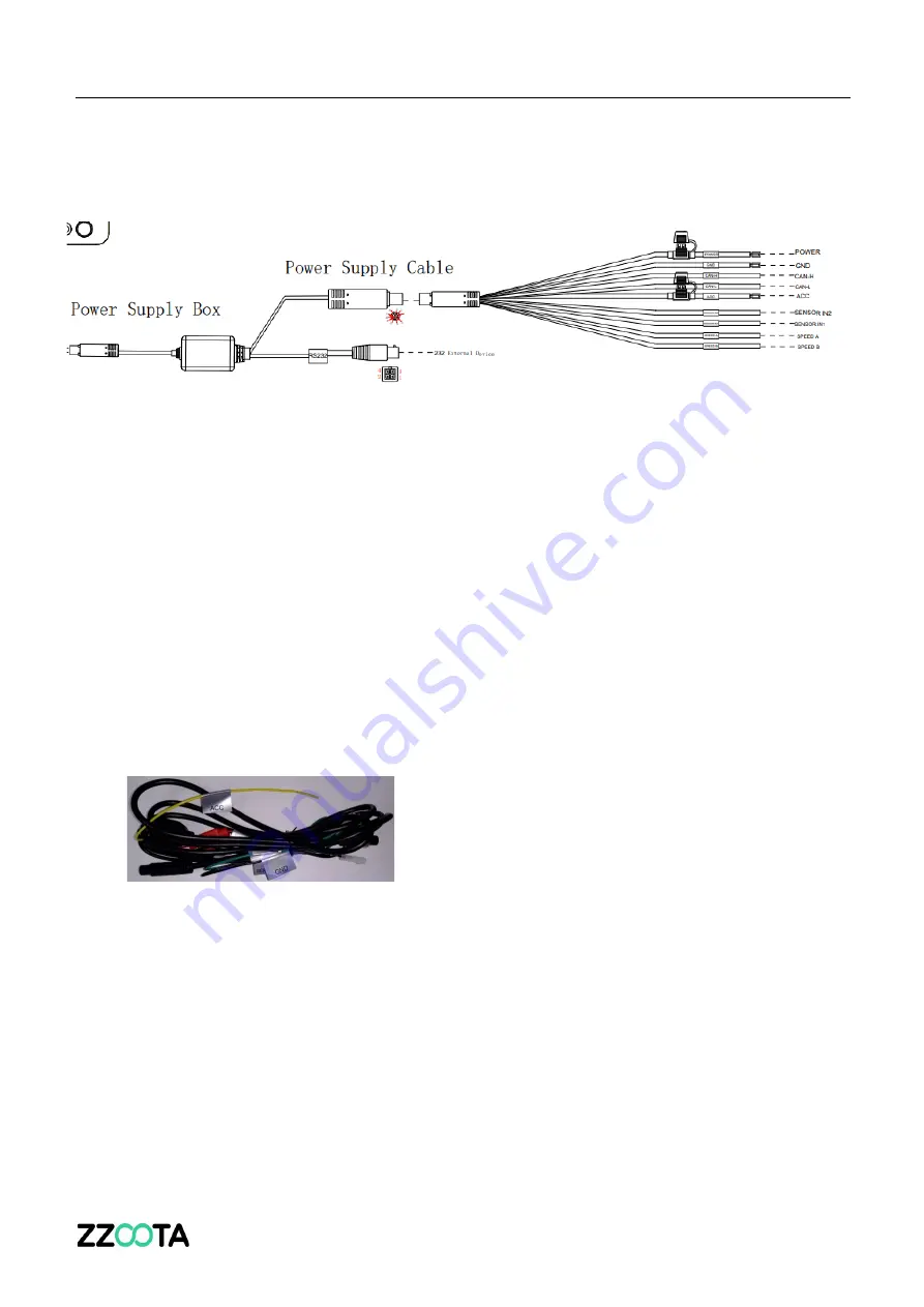
Power supply, ignition, and IO signal 


The power supply should come from batteries or direct current.


1. When in a vehicle, power supply can come from the vehicle batteries through the fuse box. 
2. When using a battery or DC power supply, the output voltage range should be within 9-36V.  
3. ACC should connect to vehicle ignition controller. 

 
Speed signal and Serial ports 


The vehicle speed can be read from an CAN port or GPS. 
 

Connect power supply and ignition signal wire 

1.


Connect the ACC line on the 10PIN power cord with the vehicle ignition signal line.  


Important hint: 

1.


Before connecting the ACC cable to the ignition wire of the vehicle, make sure that the 
vehicle is turned off. 

2.


The power cord should be directly connected to the vehicle battery. The power cord is 
still 9-36V after the ACC is turned off. 


Содержание SharpAi-ADAS

Страница 1: ...SharpAi ADAS SharpAi DSM DSM 2 SharpAi 3 Camera Installation Guide ...

Страница 2: ...es app before installation Apple Store https apps apple com za app veyes id1444251371 Google Play Store https play google com store apps details id com streamaxtech mdvr smartpad hl en _AU gl US USERNAME admin PASSWORD admin ...

Страница 3: ...Page 3 Overview Schematic Diagram of System Connection Power Supply through OBD ...

Страница 4: ...Page 4 Schematic Diagram of System Connection Power Supply through Wire What s in the box ...

Страница 5: ...Page 5 Installation Overview ...

Страница 6: ...Page 6 A recent installation example ...

Страница 7: ...nect to vehicle ignition controller Speed signal and Serial ports The vehicle speed can be read from an CAN port or GPS Connect power supply and ignition signal wire 1 Connect the ACC line on the 10PIN power cord with the vehicle ignition signal line Important hint 1 Before connecting the ACC cable to the ignition wire of the vehicle make sure that the vehicle is turned off 2 The power cord should...

Страница 8: ...indicator icon on the ADAS to light up When the two indicator icons turn green and are always on it indicates that the ADAS is operating correctly If there is no Wi Fi connection request after a 2 min period the Wi Fi will be automatically turned off to reduce power consumption After turning off ACC the device will enter a shutdown countdown instead of immediately shutting down IMPORTANT PLEASE RE...

Страница 9: ...covered by the wiper range o This ensures the vision is clear of dirt and bugs o On some vehicles this is not possible BEFORE FINAL ATTACHMENT Check the live view image on the Veyes app Follow the procedure outlined below Make sure there is no obstruction Mark the location on the glass with a pen Make sure the ADAS camera is o Horizontal and o Parallel and square to the ground ...

Страница 10: ... inclination angle of the level to center the bubble Attach the bracket with the connection to the camera unit with the toothed side facing left Tear off the 3M adhesive film on the bracket to attach the bracket horizontally on the front windshield with the level as reference and then press the bracket for 10s to ensure there are no bubbles between the bracket and the glass ...

Страница 11: ... the figure below Connect the ADAS camera to the bracket with the front side facing inward with the teeth on the left side of the bracket engaged with those on the left inner side of the ADAS camera Tighten the bracket stud clockwise with a PH2 cross screwdriver before tightening first adjust the ADAS camera to be vertical ...

Страница 12: ... back and forth to center the bubble in the level indicating that the ADAS camera is vertical Fasten the bracket stud to ensure that the angle of the ADAS camera will not move easily Remove the level and fix the ADAS camera in place ...

Страница 13: ...he Wi Fi network is the Serial Number s n found on the side of the unit Example ST 002B014F94 2 Enter the ADAS Camera Install Height AC Height off the ground 1 Log into VEYES 2 Select Preferences 3 Select Alarm 4 Select AI App 5 Select Algorithm Measure ADAS lens height from the ground ...

Страница 14: ...n the operation interface of the Veyes app to enter the preview interface and double click channel 2 to enlarge the cockpit screen Open the card slot panel at the bottom of the ADAS Insert the L shaped socket head wrench into the cabin camera angle adjustment hole to adjust the angle of the cabin camera lens Adjust the cabin camera lens to meet the following conditions 1 The centre console in the ...

Страница 15: ...ehicle is displayed at the left right lower corner of the screen 4 ADAS Calibration Left Right Indicators Setup Vehicle Height Confirmation 1 On the home screen tap Preview The Preview screen is displayed 2 Tap AI Calibration on the lower left corner 3 Tap ADAS for calibration ...

Страница 16: ...Page 16 4 Tap channel 1 5 Tap Calibration 6 Confirm ADAS camera is center horizontal and camera lens is under the windshield wiper coverage 7 Tap Next ...

Страница 17: ...tal ground clearance of the front lens unit cm or inch the height is measured as shown in the figure below 9 Tap Next 10 Tap Next tap Learn more to learn how to calibrate the ADAS camera Ground clearance of the ADAS lens cm inch ...

Страница 18: ...d source of speed from Satellite Pulse OBD and ATrack 14 Select the required IO for the left right turn signal in Left Turn Right Turn respectively Left Turn IO2 Right Turn IO1 15 Tap the required signal source type from Source Voltage and Source Pulse 16 Tap Next ...

Страница 19: ...cm o To achieve this ensure the DSM is No higher than the drivers chin Not too low to prevent the steering wheel obstructing the vision DSM ALIGNMENT BEFORE FINAL ATTACHMENT Check the live view image on the Veyes app Follow the procedure outlined below When in Preview mode adjust the angle of the DSM to ensure o Drivers face is in the middle o Bottom edge of the picture needs to be below drivers c...

Страница 20: ...ition remove the protective film off the DSM lens FYI The numbered base plate adjustment screw is on the bottom of the DSM and cannot be changed after final attachment To Preview the image An example of correct alignment ...

Страница 21: ...xt steps to correct Step 1 Select Preferences top right corner Step 2 Select Camera Setup Step 3 Select channel 3 bottom left and then edit Install Angle Mirror or Flip to achieve the correct setup DSM CALIBRATION To put the DSM into Calibration Mode follow these steps ...

Страница 22: ...Page 22 During Calibration Calibration frame is Red num 301 calibrate false Calibration Completed Calibration frame is Blue num 301 ...

Страница 23: ...d into the A pillar truck frame o If attached to the trim only the DSM will not stay in position The screws do not need to be vertical to each other REVIEW THE LIVE VISION AGAIN TO CHECK THE CORRECT ALIGNMENT DOUBLE CHECK THAT BOTH THE ADAS and DSM ARE OUT OF CALIBRATION MODE NORMAL MODE ...

Страница 24: ...Page 24 Some recent installation photos ...

Страница 25: ...Page 25 ...

Страница 26: ...Page 26 ...

Страница 27: ...Page 27 ...

Страница 28: ...Page 28 Intentionally left blank ...

Страница 29: ...Page 29 ...

Отзывы: