Chapter 7 Monitor
ZyWALL USG Series User’s Guide
201
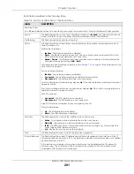
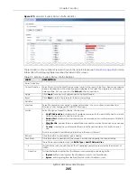
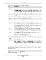
Each field is described in the following table.
Table 38 Monitor > System Status > Interface Status
LABEL
DESCRIPTION
Interface Status
If an Ethernet interface does not have any physical ports associated with it, its entry is displayed in light gray text.
Name
This field displays the name of each interface. If there is an
Expand
icon (plus-sign) next to the
name, click this to look at the status of virtual interfaces on top of this interface.
Port/Binding
This field displays the physical port number.
Status
This field displays the current status of each interface. The possible values depend on what
type of interface it is.
For Ethernet interfaces:
•
Inactive
- The Ethernet interface is disabled.
•
Down
- The Ethernet interface does not have any physical ports associated with it or the
Ethernet interface is enabled but not connected.
•
Speed / Duplex
- The Ethernet interface is enabled and connected. This field displays the
port speed and duplex setting (
Full
or
Half
).
For cellular (mobile broadband) interfaces, see
the Web Help for the
status that can appear.
For the auxiliary interface:
•
Inactive
- The auxiliary interface is disabled.
•
Connected
- The auxiliary interface is enabled and connected.
•
Disconnected
- The auxiliary interface is not connected.
For virtual interfaces, this field always displays
Up
. If the virtual interface is disabled, it does not
appear in the list.
For VLAN and bridge interfaces, this field always displays
Up
. If the VLAN or bridge interface is
disabled, it does not appear in the list.
For PPP interfaces:
•
Connected
- The PPP interface is connected.
•
Disconnected
- The PPP interface is not connected.
If the PPP interface is disabled, it does not appear in the list.
For WLAN interfaces:
•
Up
- The WLAN interface is enabled.
•
Down
- The WLAN interface is disabled.
HA Status
This field displays the status of the interface in the virtual router.
•
Active
- This interface is the master interface in the virtual router.
•
Stand-By
- This interface is a backup interface in the virtual router.
•
Fault
- This VRRP group is not functioning in the virtual router right now. For example, this
might happen if the interface is down.
•
n/a
- Device HA is not active on the interface.
Zone
This field displays the zone to which the interface is assigned.
IP Addr/Netmask
This field displays the current IP address and subnet mask assigned to the interface. If the IP
address and subnet mask are 0.0.0.0, the interface is disabled or did not receive an IP address
and subnet mask via DHCP.
If this interface is a member of an active virtual router, this field displays the IP address it is
currently using. This is either the static IP address of the interface (if it is the master) or the
management IP address (if it is a backup).
Содержание USG110
Страница 27: ...27 PART I User s Guide ...
Страница 67: ...Chapter 2 Initial Setup Wizard ZyWALL USG Series User s Guide 67 Figure 41 Object Service Service Group HTTPS ...
Страница 195: ...195 PART II Technical Reference ...
Страница 282: ...Chapter 9 Wireless ZyWALL USG Series User s Guide 282 Figure 229 Configuration Wireless AP Management AP Group Add Edit ...
Страница 309: ...Chapter 10 Interfaces ZyWALL USG Series User s Guide 309 ...
Страница 310: ...Chapter 10 Interfaces ZyWALL USG Series User s Guide 310 Configuration Network Interface Ethernet Edit External Type ...
Страница 312: ...Chapter 10 Interfaces ZyWALL USG Series User s Guide 312 Configuration Network Interface Ethernet Edit Internal Type ...
Страница 313: ...Chapter 10 Interfaces ZyWALL USG Series User s Guide 313 ...
Страница 314: ...Chapter 10 Interfaces ZyWALL USG Series User s Guide 314 Figure 246 Configuration Network Interface Ethernet Edit OPT ...
Страница 315: ...Chapter 10 Interfaces ZyWALL USG Series User s Guide 315 Configuration Network Interface Ethernet Edit OPT ...
Страница 334: ...Chapter 10 Interfaces ZyWALL USG Series User s Guide 334 Figure 255 Configuration Network Interface PPP Add ...
Страница 342: ...Chapter 10 Interfaces ZyWALL USG Series User s Guide 342 Figure 257 Configuration Network Interface Cellular Add Edit ...
Страница 357: ...Chapter 10 Interfaces ZyWALL USG Series User s Guide 357 Figure 267 Configuration Network Interface VLAN Add Edit ...
Страница 358: ...Chapter 10 Interfaces ZyWALL USG Series User s Guide 358 ...
Страница 372: ...Chapter 10 Interfaces ZyWALL USG Series User s Guide 372 Figure 269 Configuration Network Interface Bridge Add Edit ...
Страница 373: ...Chapter 10 Interfaces ZyWALL USG Series User s Guide 373 ...
Страница 565: ...Chapter 25 Walled Garden ZyWALL USG Series User s Guide 565 Figure 399 Walled Garden Login Example ...
Страница 613: ...Chapter 30 IPSec VPN ZyWALL USG Series User s Guide 613 Figure 431 Configuration VPN IPSec VPN VPN Connection Add Edit ...
Страница 621: ...Chapter 30 IPSec VPN ZyWALL USG Series User s Guide 621 Figure 433 Configuration VPN IPSec VPN VPN Gateway Add Edit ...
Страница 651: ...Chapter 31 SSL VPN ZyWALL USG Series User s Guide 651 Figure 454 Create a Web Application SSL Application Object ...
Страница 664: ...Chapter 32 SSL User Screens ZyWALL USG Series User s Guide 664 4 Next run and log into the SecuExtender client ...
Страница 730: ...Chapter 38 IDP ZyWALL USG Series User s Guide 730 Figure 508 Configuration UTM Profile IDP Custom Signatures Add Edit ...
Страница 784: ...Chapter 42 Device HA ZyWALL USG Series User s Guide 784 Figure 541 Configuration Device HA Device HA ...
Страница 929: ...Chapter 44 System ZyWALL USG Series User s Guide 929 Figure 648 Configuration System WWW Login Page Desktop View ...
Страница 978: ...Chapter 45 Log and Report ZyWALL USG Series User s Guide 978 Figure 696 Log Category Settings AC ...
Страница 1011: ...Chapter 47 Diagnostics ZyWALL USG Series User s Guide 1011 Figure 720 Maintenance Diagnostics Network Tool ...

