background image

NetNumen™ U31 R06 Hardware Installation Guide

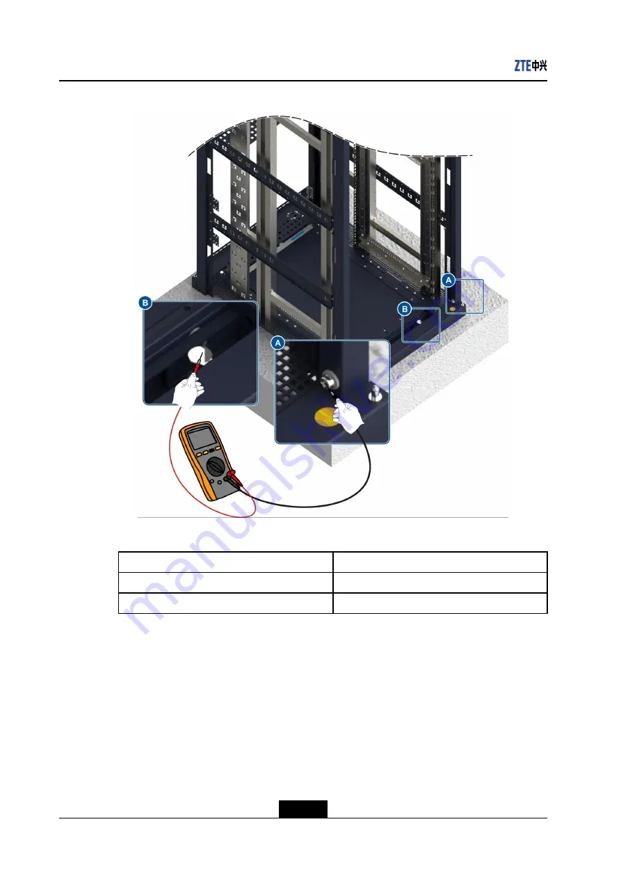
Figure 5-34 Measuring Resistance of the Cabinet

10. Perform the following procedures as required:

To...

Do...

Install a single cabinet

Go to step

14.

Install multiple cabinets

Go to step

11.

11. Install cabinets side by side.

The spacing between the neighboring cabinets in a row should be smaller than 3 mm.

The side of cabinet rows that are along the walkway must be aligned with a deviation

less than 5 mm, see

Figure 5-35

.

5-26

SJ-20141121113158-006|2014-12-20 (R1.0)

ZTE Proprietary and Confidential

Содержание NetNumen U31 R06

Страница 1: ... Management System Hardware Installation Guide Version V12 14 30 ZTE CORPORATION No 55 Hi tech Road South ShenZhen P R China Postcode 518057 Tel 86 755 26771900 Fax 86 755 26770801 URL http support zte com cn E mail support zte com cn ...

Страница 2: ... infringement ZTE CORPORATION and its licensors shall not be liable for damages resulting from the use of or reliance on the information contained herein ZTE CORPORATION or its licensors may have current or pending intellectual property rights or applications covering the subject matter of this document Except as expressly provided in any written license between ZTE CORPORATION and its licensee th...

Страница 3: ... 7 Chapter 7 Assembly Installation in a Cabinet 7 1 7 1 Installing an E4140 Shelf 7 1 7 2 Installing Boards 7 3 7 2 1 Removing a Blank Panel 7 4 7 2 2 Installing a Board 7 6 Chapter 8 Installation of Internal Power Cables and Grounding Cables 8 1 8 1 Power Supply System in a Cabinet 8 1 8 2 Installing Cables for an E4140 Shelf 8 3 Chapter 9 Signal Cable Installation 9 1 9 1 Signal Cable Installati...

Страница 4: ... the Cabinets 12 2 12 3 Checking the Power Cables and Grounding Cables 12 2 12 4 Checking the Signal Cables 12 3 12 5 Checking the Other auxiliary Devices 12 3 Chapter 13 System Power On 13 1 13 1 Powering on the Cabinet 13 1 13 2 Powering on the E4140 Shelves 13 3 Chapter 14 Site Clean Up 14 1 Appendix A Making a Power Cable and a Grounding Cable A 1 Appendix B Making a Network Cable B 1 Figures ...

Страница 5: ...tions such as preparing construction conditions checking installation environment and unpacking and inspecting goods so that the later installation process can be smooth and efficient For the hardware installation flow see Figure 1 1 1 1 SJ 20141121113158 006 2014 12 20 R1 0 ZTE Proprietary and Confidential ...

Страница 6: ...NetNumen U31 R06 Hardware Installation Guide Figure 1 1 Hardware Installation Flow 1 2 SJ 20141121113158 006 2014 12 20 R1 0 ZTE Proprietary and Confidential ...

Страница 7: ... install the equipment if the installation environment is unsatisfactory l Architectural conditions Check the size height load bearing capacity and layout of the equipment room l Environmental conditions Check illumination air conditioning ventilation antistatic measures shockproof measures lightning protection measures and fire fighting devices of the equipment room l Power supply conditions Chec...

Страница 8: ...tion refer to Table 2 1 Note Instruments and meters are subject to local standards The pictures in the table are for reference only The meters cannot be used unless strictly calibrated and proven qualified Table 2 1 Tools and Meters Picture Name Purpose Cross head screw driver Tightens cross head screws Flathead screw driver Tightens flathead screws Adjustable wrench Tightens bolts Torque wrench T...

Страница 9: ...ecks vertical deviation of a cabi net Marker pen Marks the positions of drilled holes on the floor Powder marker Marks lines on the ground to de termine the position where a socket bolt is installed Claw hammer Installs socket bolts and opens wooden cases Percussion drill Drills holes Vacuum cleaner Cleans installation holes and the floor 2 3 SJ 20141121113158 006 2014 12 20 R1 0 ZTE Proprietary a...

Страница 10: ...n of ca bles and electric performance in dexes of devices such as voltage current and electric resistance Current clamp me ter Measures the current in a cable un der the condition that the loading op eration is not interrupted Crystalhead crimp ing pliers Crimps crystalheads of network ca bles Coaxial cable crimping pliers Crimps the metal sheath at the end of a coaxial cable Wire strippers Strips...

Страница 11: ...for working at heights Punch Used to locate a drill bit for making an indentation at the hole location 2 3 Required Documents The following documents must be prepared before installation l Engineering design documents and packing lists l Manuals shipped with the products l Unpacking Inspection Guide of Core Network Products l Environment Acceptance Report of Core Network Products l Core Network Pr...

Страница 12: ...NetNumen U31 R06 Hardware Installation Guide This page intentionally left blank 2 6 SJ 20141121113158 006 2014 12 20 R1 0 ZTE Proprietary and Confidential ...

Страница 13: ...aw hammer diagonal pliers a paper knife antistatic gloves or an ESD wrist strap are ready Steps 1 Check the total number of equipment in accordance with the Packing List and then verify that the outer packing is complete 2 Remove the outer packing of the wooden case a Move the wooden case with a fork truck to the cabinet installation site in the equipment room b Open all tongue pieces with a flath...

Страница 14: ...move foam corner protectors foam edge protectors and plastic package 3 Remove the outer packing of the carton see Figure 3 2 a Cut the packing straps of a carton by using diagonal pliers b Cut the adhesive tapes sealing the carton c Open the carton and then take out the foam board and board boxes Figure 3 2 Removing the Outer Packing of a Carton 1 Carton label 2 Packing strap 3 Carton 3 2 SJ 20141...

Страница 15: ...Figure 3 3 Figure 3 3 Removing the Board Package 1 ESD wrist strap c For the board that is not installed immediately put it back in its original package and then seal the package 5 Check to ensure that the equipment is in good condition and the quantity is correct before equipment hand over and storage End of Steps 3 3 SJ 20141121113158 006 2014 12 20 R1 0 ZTE Proprietary and Confidential ...

Страница 16: ...NetNumen U31 R06 Hardware Installation Guide This page intentionally left blank 3 4 SJ 20141121113158 006 2014 12 20 R1 0 ZTE Proprietary and Confidential ...

Страница 17: ... removed in the same way Removing the front door is used as an example in this procedure Prerequisite A cross head screwdriver is ready Steps 1 Open the door lock and then open the cabinet door see Figure 4 1 Figure 4 1 Opening the Door Lock 2 Disconnect the end of the grounding cable on the cabinet by using a cross head screwdriver it is recommended that only the end connected to the cabinet is d...

Страница 18: ... cabinet door see Figure 4 3 a Hold the door with your right hand b Pull down the spring pin located in the middle part of the door with your left hand and then hang the spring pin in the gap on one side of the door c Pull down the spring pin on the upper part of the door d Lift the door upwards and then move the door outwards 4 2 SJ 20141121113158 006 2014 12 20 R1 0 ZTE Proprietary and Confident...

Страница 19: ... 2 Front door Note Put the cabinet at a safe place Ensure that the lock of the cabinet door is opened which prevents the lock rod on the lower part of the door from being distorted because of pressure End of Steps 4 3 SJ 20141121113158 006 2014 12 20 R1 0 ZTE Proprietary and Confidential ...

Страница 20: ...NetNumen U31 R06 Hardware Installation Guide This page intentionally left blank 4 4 SJ 20141121113158 006 2014 12 20 R1 0 ZTE Proprietary and Confidential ...

Страница 21: ...conductive floor Install the cabinet on the adjustable base Use the adjustable base to install the cabinet on the concrete floor of the equipment room see Figure 5 1 The equipment room has no static conductive floor Install the cabinet on the floor Install the cabinet directly on the concrete floor of the equipment room see Figure 5 2 Figure 5 1 Installing the Cabinet on the Adjustable Base 5 1 SJ...

Страница 22: ...Base 5 2 Installing the Cabinet on the Floor 5 18 5 1 Installing the Cabinet on the Adjustable Base This procedure describes how to install the cabinet on the adjustable base Adjust the base height and mount the base to make its surface in level with the static conductive floor 5 2 SJ 20141121113158 006 2014 12 20 R1 0 ZTE Proprietary and Confidential ...

Страница 23: ...y l Instruments such as cross head screwdriver tape measure angle square spirit level powder marker marker pen percussion drill vacuum cleaner adjustable spanner torque spanner socket spanner claw hammer punch multimeter and ladder are ready l Spacer shims insulating gaskets M12 90 bolts an M12 90 bolt contains a spring washer a gasket and an insulating washer M12 35 bolts an M12 35 bolt contains ...

Страница 24: ...oor framework at the colliding position Adjustable bases fall into three types For types of the adjustable base refer to Table 5 2 Table 5 2 Adjustable Heights Adjustable Base Type Adjustable Heights Type A 160 mm 240 mm Type B 240 mm 390 mm Type C 390 mm 690 mm The three types of adjustable bases have the same structure For the overview of an adjustable base of type A see Figure 5 4 5 4 SJ 201411...

Страница 25: ...t tools and line drawing tools to mark the installation holes for the adjustable base l For the position of holes for installing a single cabinet see Figure 5 5 Figure 5 5 Marking Holes for Installing a Single Cabinet Unit mm 1 Installation hole 2 Wall l For the installation holes of socket bolts for the adjustable bases to install multiple cabinets see Figure 5 6 5 5 SJ 20141121113158 006 2014 12...

Страница 26: ...stallation holes for the base by using a marker pen see Figure 5 7 If the holes do not match adjust the holes so that the lines drawn in step 2 are correct Figure 5 7 Marking Installation Holes Using the Drilling Template 4 In accordance with the position of the socket bolt marked on the floor make an indentation at the hole location first by using a punch to help locate the drill bit see Figure 5...

Страница 27: ... to drill holes Use the vacuum cleaner to remove the dust inside and outside the holes see Figure 5 9 Figure 5 9 Drilling a Hole 1 Vacuum cleaner 2 Percussion drill 6 Remove the bolt spring washer insulating washer and gasket of the AN01 socket bolt For the overview of AN01 socket bolt see Figure 5 10 5 7 SJ 20141121113158 006 2014 12 20 R1 0 ZTE Proprietary and Confidential ...

Страница 28: ... completely see Figure 5 11 Figure 5 11 Hammering a Socket Bolt Mounting the adjustable base 8 Measure the height between the concrete floor and the surface of the static conductive floor by using a tape measure 9 Adjust the adjustable base to make the scale indication on the base equal to the height of the static conductive floor see Figure 5 12 The tightening torque of a height locking bolt shou...

Страница 29: ...t of an Adjustable Base 1 Movable bracket 2 Height locking M12 25 bolt 3 Fixed bracket 10 Secure the adjustable base see Figure 5 13 Note The tightening torque of a bolt should reach 75 N m 5 9 SJ 20141121113158 006 2014 12 20 R1 0 ZTE Proprietary and Confidential ...

Страница 30: ...washer 3 Gasket 4 Insulating washer 5 Adjustable base 6 Insulating gasket 7 Concrete floor 11 Remove M12 35 bolts from the adjustable base by using an adjustable wrench Remove spring washers and gaskets from the bolts see Figure 5 14 5 10 SJ 20141121113158 006 2014 12 20 R1 0 ZTE Proprietary and Confidential ...

Страница 31: ...s by using a spirit level The deviation should be less than 3 mm If the adjustable base is not level place a spacer shim between the base and the concrete floor see Figure 5 15 Figure 5 15 Adjusting the Level of the Adjustable Base 1 Spirit level 2 Spacer shim 13 Perform the following procedures as required 5 11 SJ 20141121113158 006 2014 12 20 R1 0 ZTE Proprietary and Confidential ...

Страница 32: ...e adjustable bases by using the spirit level see Figure 5 16 Figure 5 16 Adjusting the Level of Multiple Adjustable Bases 1 Spacer shim 2 Spirit level 15 Use the multimeter to measure the resistance between the adjustable base and the concrete floor see Figure 5 17 Note The resistance value must be greater than 5 MΩ 5 12 SJ 20141121113158 006 2014 12 20 R1 0 ZTE Proprietary and Confidential ...

Страница 33: ...the cabinet 16 Lift the cabinet onto the adjustable base 17 Align the installation holes at the bottom of the cabinet with the installation holes on the surface of the cabinet 18 Secure the cabinet with bolts see Figure 5 18 5 13 SJ 20141121113158 006 2014 12 20 R1 0 ZTE Proprietary and Confidential ...

Страница 34: ...stable base 19 Measure the level and the verticality of the cabinet with the spirit level The horizontal and vertical deviations should be less than 3 mm If the cabinet is not level adjust the fine adjustment screw by using the socket spanner see Figure 5 19 5 14 SJ 20141121113158 006 2014 12 20 R1 0 ZTE Proprietary and Confidential ...

Страница 35: ...tall a single cabinet Go to step 24 Install multiple cabinets Go to step 21 21 Install cabinets side by side The spacing between the neighboring cabinets in a row should be smaller than 3 mm The sides of cabinet rows that are along the walkway must be aligned with a deviation less than 5 mm see Figure 5 20 5 15 SJ 20141121113158 006 2014 12 20 R1 0 ZTE Proprietary and Confidential ...

Страница 36: ...ace Between Side by Side Cabinets 22 Connect neighboring cabinets with junction kits see Figure 5 21 Figure 5 21 Connecting Neighboring Cabinets 1 Junction kit 2 M4 12 combination screw 5 16 SJ 20141121113158 006 2014 12 20 R1 0 ZTE Proprietary and Confidential ...

Страница 37: ... are under the cable ladder in the equipment room see Figure 5 22 Figure 5 22 Installing the Shockproof Assembly 1 1 Horizontal support 2 Vertical support 3 Cable ladder 4 M12 25 M8 25 hexagon socket cap head bolt Spring washer gasket and insulating washer 5 Insulating gasket 6 Lock rod M8 hexagon nut spring washer and gasket 7 Bolt M8 nut spring washer and gasket l For the shockproof assembly ins...

Страница 38: ...agon nut spring washer and gasket 7 Bolt M8 nut spring washer and gasket 25 Restore the static conductive floor Adjust the support kit for the static conductive floor again Install the static conductive floor Note If bottom routing is used ensure that cabling is complete End of Steps 5 2 Installing the Cabinet on the Floor This procedure describes how to install the cabinet on the concrete floor 5...

Страница 39: ...eady l Tools such as cross head screwdriver tape measure spirit level angle square powder marker marker pen percussion drill vacuum cleaner adjustable spanner torque spanner socket spanner claw hammer punch multimeter and ladder are ready l Spacer shims insulating gaskets M12 90 bolts an M12 90 bolt contains a spring washer a gasket and an insulating washer are ready Context For the installation p...

Страница 40: ...cket bolts to install a single cabinet see Figure 5 25 Figure 5 25 Marking Holes for Installing a Single Cabinet Unit mm 1 Installation hole 2 Wall l For the installation holes of socket bolts to install multiple cabinets see Figure 5 26 Figure 5 26 Marking Holes for Installing Multiple Cabinets Unit mm 1 Installation hole 2 Wall 5 20 SJ 20141121113158 006 2014 12 20 R1 0 ZTE Proprietary and Confi...

Страница 41: ...ion Holes Using the Drilling Template 3 In accordance with the position of the socket bolt marked on the floor make an indentation at the hole location first by using a punch to help locate the drill bit see Figure 5 28 Figure 5 28 Drilling Indentations 4 Adjust the locating rod that determines the depth of the hole and then press the percussion drill downward vertically to drill holes Use the vac...

Страница 42: ...r the overview of AN01 socket bolt see Figure 5 30 Figure 5 30 Socket Bolt AN01 1 M12 90 bolt 2 Spring washer 3 Gasket 4 Insulating washer 5 Expansion tube 6 Install the socket bolt vertically into the hole Hammer the socket bolt by using the claw hammer until the expansion tube enters the hole completely see Figure 5 31 5 22 SJ 20141121113158 006 2014 12 20 R1 0 ZTE Proprietary and Confidential ...

Страница 43: ... planned position to align the installation holes at the bottom of the cabinet with the corresponding socket bolts b Lift one side of the cabinet and then place two insulating gaskets under the cabinet c Secure the cabinet with M12 90 bolts by increasing the tightening torque of the bolts to 75 N m 5 23 SJ 20141121113158 006 2014 12 20 R1 0 ZTE Proprietary and Confidential ...

Страница 44: ...ket 6 Insulating washer 8 Measure the level and the verticality of the cabinet with the spirit level The horizontal and vertical deviations should be less than 3 mm If the cabinet is not level adjust the fine adjustment screw by using the socket spanner see Figure 5 33 5 24 SJ 20141121113158 006 2014 12 20 R1 0 ZTE Proprietary and Confidential ...

Страница 45: ...net 1 Spirit level 2 Socket spanner 3 Inching bolt 9 Use the multimeter to measure the resistance between the cabinet and the ground see Figure 5 34 Note The resistance value must be greater than 5 MΩ 5 25 SJ 20141121113158 006 2014 12 20 R1 0 ZTE Proprietary and Confidential ...

Страница 46: ...abinet Go to step 14 Install multiple cabinets Go to step 11 11 Install cabinets side by side The spacing between the neighboring cabinets in a row should be smaller than 3 mm The side of cabinet rows that are along the walkway must be aligned with a deviation less than 5 mm see Figure 5 35 5 26 SJ 20141121113158 006 2014 12 20 R1 0 ZTE Proprietary and Confidential ...

Страница 47: ... to step 9 must be implemented immediately after a cabinet is installed Figure 5 35 Space Between Side by Side Cabinets 12 Connect neighboring cabinets with junction kits see Figure 5 36 5 27 SJ 20141121113158 006 2014 12 20 R1 0 ZTE Proprietary and Confidential ...

Страница 48: ...w are in an acceptable range The deviation should be less than 3 mm If it does not meet the requirement adjust cabinets 14 Optional Install a shockproof assembly on the cabinet if necessary l For the shockproof assembly installation when all the installation holes are under the cable ladder in the equipment room see Figure 5 37 5 28 SJ 20141121113158 006 2014 12 20 R1 0 ZTE Proprietary and Confide...

Страница 49: ...p head bolt Spring washer gasket and insulating washer 5 Insulating gasket 6 Lock rod M8 hexagon nut spring washer and gasket 7 Bolt M8 nut spring washer and gasket l For the shockproof assembly installation when the vertical connection plates are not close to the cable ladder see Figure 5 38 5 29 SJ 20141121113158 006 2014 12 20 R1 0 ZTE Proprietary and Confidential ...

Страница 50: ... Vertical support 3 Cable ladder 4 M12 25 M8 25 hexagon socket cap head bolt Spring washer gasket and insulating washer 5 Insulating gasket 6 Lock rod M8 hexagon nut spring washer and gasket 7 Bolt M8 nut spring washer and gasket End of Steps 5 30 SJ 20141121113158 006 2014 12 20 R1 0 ZTE Proprietary and Confidential ...

Страница 51: ...s in parallel so that the whole set of equipment becomes an equipotential body Table of Contents Power Supply System of a Cabinet 6 1 Cabling Requirements 6 3 Installing Power Cables and Grounding Cables 6 7 6 1 Power Supply System of a Cabinet Power Supply System The power supply system of a cabinet consists of the AC power supply subsystem DC power supply subsystem DC power distribution subsyste...

Страница 52: ... terminal 2 RTN output terminal 3 48 V 60 V output terminal For the relationship between input terminals and output terminals of the unified PDU refer to Table 6 1 Table 6 1 Relationship Between Input Terminals and Output Terminals Area A Area B Way Number Input Terminal Output Terminal Output Terminal Input Terminal 48 V Ⅰ 48 V A 1 2 48 V B 1 2 48 V Ⅰ Way 1 48 VRTN Ⅰ 48 VRTN A 1 2 48 VRTN B 1 2 4...

Страница 53: ...rent on one way is 60 A Output terminal 5 10 The maximum output current on one way is 60 A Breakers of other rated currents can also be configured as needed The maximum input current on each way is 100 A 6 2 Cabling Requirements Routing Principles l Power cables and grounding cables should be routed in a smooth and straight manner see Figure 6 3 Figure 6 3 Routing of Power Cables and Grounding Cab...

Страница 54: ...ngle of 45 degrees or 90 degrees see B of Figure 6 4 O type terminals must not be overlaid see C of Figure 6 4 The larger O type terminal cannot be placed on the smaller one see D of Figure 6 4 Figure 6 4 Installation Modes of O Type Terminals l The horizontal distance between power cables or grounding cables and other cables should be greater than 300 mm see Figure 6 5 6 4 SJ 20141121113158 006 2...

Страница 55: ...nd straight manner without any crossover or cable coiling Binding Principles l Power cables and grounding cables should be bundled separately from other cables l The distance between two neighboring ties should be 200 mm l Avoid cables from being squeezed or stretched by rotatable parts such as a door Do not bind the cables at the bends see Figure 6 6 Figure 6 6 Cable Binding l Cable ties should f...

Страница 56: ...top along the cable ladder see Figure 6 7 Figure 6 7 Top Routing of a Cabinet 1 Cable ladder 2 Cover plate for power cables 3 Unified PDU Bottom Routing Principles Power cables and grounding cables are routed from the bottom of the DC power distribution box to the cabinet bottom through the static conductive floor see Figure 6 8 6 6 SJ 20141121113158 006 2014 12 20 R1 0 ZTE Proprietary and Confide...

Страница 57: ...x to cabinets If a DC power distribution box is not available install cables as follows l Connect the 48 V 60 V power cable of the cabinet to the DC distribution panel or the 48 V 60 V negative busbar of the DC power supply l Connect the RTN power cable of the cabinet to the DC distribution panel or the 48 V 60 V positive busbar of the DC power supply l Connect the grounding cable of the cabinet t...

Страница 58: ...all the power cables and the grounding cable at the cabinet side see Figure 6 7 and Figure 6 8 5 Install the power cables and the grounding cable at the DC power distribution box a Connect the yellow green grounding cable to the PE connection terminal of the DC power distribution box b Connect the blue power cable to the 48 V 60 V connection terminal of the DC power distribution box c Connect the ...

Страница 59: ...Do not move or install a shelf containing boards Do not apply force on vulnerable parts such as extractors on a power module cable tray or vents when moving or installing a shelf Failure to comply can result in damage or distortion At least two persons are required to install the shelf Failure to comply can result in personal injury or equipment damage Prerequisite l Brackets and floating nuts hav...

Страница 60: ... installing an E4140 shelf see Figure 7 1 Figure 7 1 Installing an E4140 Shelf 1 Bracket 2 M6 20 combination screw 3 E4140 shelf 4 Set the jumpers for the New Chassis Data Module NCDM Figure 7 2 shows the jumpers of the NCDM board For the function of each jumper refer to Table 7 1 Figure 7 2 Jumpers of the NCDM Board 7 2 SJ 20141121113158 006 2014 12 20 R1 0 ZTE Proprietary and Confidential ...

Страница 61: ...d are 1 3 4 5 and 8 l If the rack No is 3 and the shelf No is 1 the positions where jumper blocks are needed are 3 4 and 6 Note If there are two NCDM boards in a shelf the two boards must have the same jumper settings and must be configured with the same rack and shelf information End of Steps 7 2 Installing Boards The E4140 shelf backplane supports direct interconnection between the active and st...

Страница 62: ...a blank panel with extractors Prerequisite l An ESD wrist strap or anti static gloves and a cross head screwdriver are ready l The position of the blank panel to be removed is known Steps 1 Wear the Electro Static Discharge ESD wrist strap or anti static gloves and then connect the grounding terminal of the strap into the ESD jack on the shelf For how to wear the ESD wrist strap see Figure 7 4 Fig...

Страница 63: ... the procedure for removing a rear blank panel from the shelf Figure 7 6 shows the procedure for removing a front blank panel from the shelf Figure 7 5 Removing a Rear Blank Panel 1 Extractor 2 Captive screw 3 Latch 7 5 SJ 20141121113158 006 2014 12 20 R1 0 ZTE Proprietary and Confidential ...

Страница 64: ...tall a board in an E4140 shelf by using the front board as an example Note The procedure for installing a rear board is the same as that for installing a front board For an E4140 shelf rear boards must be installed before front boards are installed Prerequisite l An ESD wrist strap or anti static gloves and a cross head screwdriver are ready l The position where the board is installed in the shelf...

Страница 65: ...memory properly installed Caution Do not directly contact the components in the board Failure to comply can result in damage to the board Do not hold the board by only catching the extractors Failure to comply can result in damage to the extractors Figure 7 7 Checking the Memory Installation If the memory bar is not in position perform the following steps to reinstall it a Move aside the extractor...

Страница 66: ... on two ends with equal strength to install the bar into the slot Verify that the extractors on two ends of the memory slot closely lock the memory bar see Figure 7 9 Caution Do not press on any board element to avoid any element falling down 7 8 SJ 20141121113158 006 2014 12 20 R1 0 ZTE Proprietary and Confidential ...

Страница 67: ...allation in a Cabinet Figure 7 9 Reinstalling the Memory Bar 3 Pull up the latches and open the upper and lower extractors completely see Figure 7 10 7 9 SJ 20141121113158 006 2014 12 20 R1 0 ZTE Proprietary and Confidential ...

Страница 68: ...l the board into the shelf and secure it in the shelf see Figure 7 11 a Hold the lower edge of the board with one hand and seize one extractor of the board with the other hand Push the board slowly along the slot rails into the shelf b Close the upper and lower extractors at the same time until the latches lock the extractors completely c Tighten the captive screws 7 10 SJ 20141121113158 006 2014 ...

Страница 69: ... Verify that there is no vacant slot in the back front part of the shelf If there is install a blank panel for the vacant slot Note The procedure for installing a blank panel is the same as that for installing a board End of Steps 7 11 SJ 20141121113158 006 2014 12 20 R1 0 ZTE Proprietary and Confidential ...

Страница 70: ...NetNumen U31 R06 Hardware Installation Guide This page intentionally left blank 7 12 SJ 20141121113158 006 2014 12 20 R1 0 ZTE Proprietary and Confidential ...

Страница 71: ...inet totally provides 20 power outputs Areas A and B each provide 10 outputs For details refer to Table 6 1 l Output terminals A1 A6 and B1 B6 are connected with the power cables of an E4140 shelf l Output terminals A7 A10 and B7 B10 are connected with the power cables of other assemblies such as disk array switch firewall and four in one assembly Figure 8 1 shows the cabling in a cabinet fully co...

Страница 72: ...Cabinet Table 8 1 Relationships Between Internal Assemblies and Control Switches of the Unified PDU Assembly Control Switch E4140 2 A1 A2 B1 and B2 E4140 1 A3 A4 B3 and B4 E4140 0 A5 A6 B5 and B6 8 2 SJ 20141121113158 006 2014 12 20 R1 0 ZTE Proprietary and Confidential ...

Страница 73: ...of the cabinet are set to OFF positions l Anti static gloves a cross head screwdriver and M6 12 combination screws are ready Steps 1 Wear anti static gloves 2 Install the grounding cables for the E4140 shelf For installing grounding cables for the E4140 shelf see Figure 8 2 Note The grounding cables cannot block the path for extracting the NCDM board at either side of the shelf a Remove the combin...

Страница 74: ... are output from Area A of the unified PDU see Figure 6 2 are routed along the right vertical cable tray of the cabinet The power cables that are output from Area B are routed along the left vertical cable tray of the cabinet a Remove the screws of the protective cover from each New Power Entry Module NPEM by using the cross head screwdriver Take down the cover b Remove the screw of each NPEM conn...

Страница 75: ...n the screws d Install the protective cover for each NPEM module and tighten the screws Figure 8 3 Installing Power Cables for the E4140 Shelf 1 Unified PDU 2 Cable tray 3 E4140 shelf 4 Vertical cable tray 5 Protective cover 6 Horizontal cable tray 4 Bind power cables that are routed along the horizontal cable tray vertical cable tray and cable trays End of Steps 8 5 SJ 20141121113158 006 2014 12 ...

Страница 76: ...NetNumen U31 R06 Hardware Installation Guide This page intentionally left blank 8 6 SJ 20141121113158 006 2014 12 20 R1 0 ZTE Proprietary and Confidential ...

Страница 77: ...bind power cables and signal cables together l Cabling in the cabinet must not affect door installation l Cables must be routed along the horizontal and vertical cable trays in a flat and straight manner without crossovers or folds l For a small number of optical fibers the fibers can be routed together with other cables and protected in soft management sets For a great number of optical fibers th...

Страница 78: ...les For how to bind the cables see Figure 9 1 Figure 9 1 Cable Binding Top Routing Principles Three anti rodent screens are provided on each side of the cabinet top see A F of Figure 9 2 The anti rodent screen should be cut in accordance with the number of cables routed out of the cabinet If the horizontal cable ladder is more than 0 8 m above the cabinet a vertical cable ladder must be used to se...

Страница 79: ...each side of the cabinet bottom The anti rodent screen should be cut in accordance with the number of cables routed out of the cabinet see Figure 9 3 The height of the signal cable bundles cannot exceed two thirds of the floor height to avoid negative effects on ventilation and heat dissipation 9 3 SJ 20141121113158 006 2014 12 20 R1 0 ZTE Proprietary and Confidential ...

Страница 80: ...gloves a cross head screwdriver diagonal pliers cable ties and a ladder are ready Context If a unified PDU in the Operation Maintenance Main Processor OMP is required you need to configure the 485 jumper and the DIP switch for the unified PDU Through the 485 jumper and the DIP switch you can set the power system type of the unified PDU and the cabinet in which the unified PDU is installed The PDUM...

Страница 81: ...for cabinet ID is used to set the ID of the cabinet in which the unified PDU is installed For the setting rules of the DIP switch refer to Table 9 1 Table 9 1 DIP Switch Location Cabinet ID Binary 1 2 3 4 1 0000 ON ON ON ON 2 0001 OFF ON ON ON 3 0010 ON OFF ON ON 4 0011 OFF OFF ON ON 5 0100 ON ON OFF ON 6 0101 OFF ON OFF ON 7 0110 ON OFF OFF ON 8 0111 OFF OFF OFF ON 9 1000 ON ON ON OFF 10 1001 OFF...

Страница 82: ...er values the unified PDU power system is 48 V DC Steps 1 Wear an ESD wrist strap or anti static gloves and then install the grounding terminal of the strap into the ESD jack on the cabinet 2 Use the cross head screwdriver to loosen the captive screws on the panel of the PDUM board Hold the handle on the panel and horizontally pull out the PDUM board see Figure 9 6 Note The PDUM board of the unifi...

Страница 83: ...er cap to connect the RS485 jumper For the settings of the RS485 jumper and the cabinet ID DIP switch see Figure 9 7 Figure 9 7 Settings of RS485 Jumper and Cabinet ID DIP Switch 4 Install the PDUM board into the unified PDU and push it in place Use the cross head screwdriver to tighten the captive screws clockwise see Figure 9 8 9 7 SJ 20141121113158 006 2014 12 20 R1 0 ZTE Proprietary and Confid...

Страница 84: ...ots of the E4140 shelf For the descriptions of the active and standby slots refer to 7 2 Installing Boards Steps 1 Wear anti static gloves 2 Confirm the installation positions of both ends and length of each cable in accordance with the cable connection table 3 Optional Make a cable For how to make a network cable refer to Appendix B Making a Network Cable 4 Attach labels on both ends of each cabl...

Страница 85: ...abinet 1 Unified PDU 2 RS485 communication cable 3 E4140 shelf 4 Vertical cabling board 5 Connecting network cable 6 Horizontal cable ladder Figure 9 10 shows the cabling connections out of the cabinet 9 9 SJ 20141121113158 006 2014 12 20 R1 0 ZTE Proprietary and Confidential ...

Страница 86: ...nication cable 5 E4140 shelf 6 Vertical cabling board 7 Horizontal cable ladder Note Point a a1 and a2 and point b identify both ends of the RS485 communication cable and RS485 cascade communication cable respectively 6 Verify that cables are correctly connected and then bind the cables End of Steps 9 10 SJ 20141121113158 006 2014 12 20 R1 0 ZTE Proprietary and Confidential ...

Страница 87: ...lling the Cabinet Side Door This procedure describes how to install the cabinet side door Note When two or more cabinets are installed side by side only the left most and right most side doors need to be installed Prerequisite l A cross head screwdriver grounding cable of the side door and M5 12 combination screws are ready l All assemblies and cables in the cabinet are installed Steps 1 Remove th...

Страница 88: ...igure 10 1 Installing the Grounding Cable of the Side Door 3 Install the side door of the cabinet see Figure 10 2 Put all screws in place on the side door and tighten them 10 2 SJ 20141121113158 006 2014 12 20 R1 0 ZTE Proprietary and Confidential ...

Страница 89: ...5 12 combination screws 2 Side door End of Steps 10 2 Installing the Front and Rear Doors This procedure describes how to install the front door and rear door Note The front door and rear door are installed in the same way 10 3 SJ 20141121113158 006 2014 12 20 R1 0 ZTE Proprietary and Confidential ...

Страница 90: ...ns into the pin holes in the cabinet 2 Repeat substeps a and b to install the rear door 3 Install the grounding cable of the door a Use the cross head screwdriver to remove the screw of the grounding point on the cabinet b Connect the other end of the grounding cable of the door and the side door to the grounding point of the cabinet see Figure 10 3 Figure 10 3 Installing the Grounding Cable of th...

Страница 91: ...stance of the Grounding Cable 4 Verify that the front and rear doors can be opened and closed properly For how to open the door of the cabinet refer to Chapter 4 Removing Cabinet Doors End of Steps 10 5 SJ 20141121113158 006 2014 12 20 R1 0 ZTE Proprietary and Confidential ...

Страница 92: ...NetNumen U31 R06 Hardware Installation Guide This page intentionally left blank 10 6 SJ 20141121113158 006 2014 12 20 R1 0 ZTE Proprietary and Confidential ...

Страница 93: ...ing and maintenance room Note The workbenches should be arranged with their edges in line The workbenches should be close to each other and all workbench surfaces should be on the same level 2 Install required terminal devices and external devices such as HUBs on workbenches 3 Connect the power cables to the terminal devices and the signal cables to the monitors 4 Connect one end of the network ca...

Страница 94: ...ion of the project site l Length of the power cable l Location of the AC adaptor l Location of any other alarm box Prerequisite l A hammer expansion tubes 4 M5 countersunk head wood screws and a pencil are ready l The installation location of the alarm box is determined l The mounting plate is removed from the back of the alarm box Steps 1 Use the mounting plate as a drill template to mark the ins...

Страница 95: ... M5 countersunk head screw 4 Mounting plate 5 Align the hooks on the side edge of the mounting plate with the holes in the alarm box to hang the alarm box onto the mounting plate see Figure 11 2 Figure 11 2 Installing an Alarm Box 1 Hook 2 Hole 11 3 SJ 20141121113158 006 2014 12 20 R1 0 ZTE Proprietary and Confidential ...

Страница 96: ...sult in damage This procedure describes how to connect the AC power cable and the network cable to the alarm box Prerequisite l The power cable and a straight through network cable RJ 45 connector are connected and routed properly l A screwdriver and cable ties are ready l Ensure that the AC socket is switched off Steps 1 Connect one end of the network cable to the network interface of the alarm b...

Страница 97: ... to install the PVC cable trunking on the wall in accordance with the installation place of the alarm box Option Description Top routing Mount the PVC cable trunking along the wall to the cable ladder so that the cables can be routed along the cable ladder and then into the cabinet Bottom routing Mount the PVC cable trunking along the wall to the floor so that the cables can be routed along the ca...

Страница 98: ...5 mm Rated voltage 300 500 V Outer diameter of the insulation layer 2 6 mm Maximum temperature resistance 70 Maximum DC resistance 20 20 Ω km Note The DC power cable and network cable should be covered by trunking and secured on the wall Cable bends should be smooth Caution Do not strain the cables because this can damage the cables This procedure describes how to connect the DC power cable and th...

Страница 99: ...cted to the terminal of the same type at both ends 3 Select either of the following cable routing methods to install the PVC cable trunking on the wall in accordance with the installation place of the alarm box Option Description Top routing Mount the PVC cable trunking along the wall to the cable ladder so that the cables can be routed along the cable ladder and then into the cabinet Bottom routi...

Страница 100: ...NetNumen U31 R06 Hardware Installation Guide This page intentionally left blank 11 8 SJ 20141121113158 006 2014 12 20 R1 0 ZTE Proprietary and Confidential ...

Страница 101: ...s ready Steps 1 Verify that the cabinets are installed in a proper position in accordance with the design requirements 2 Verify that the cabinet installation meets the shockproof requirements 3 Verify that the horizontal and vertical deviations of the cabinets are less than 3 mm and that cabinet fronts installed in a row are aligned with a deviation less than 5 mm 4 Use the multimeter to measure t...

Страница 102: ...anels are installed in the empty slots 6 Verify that the air inlets and air outlets of the fans are not blocked and the fan modules are present Caution The fan modules have been installed in a shelf when the shelf is delivered It is not allowed to remove the fan modules to prevent hardware damage End of Steps 12 3 Checking the Power Cables and Grounding Cables This procedure describes how to verif...

Страница 103: ... 2 Verify that each signal cable is connected correctly and reliably at both ends 3 Verify that no cable is routed through ventilation holes 4 Verify that all cables are routed along the horizontal and vertical cable trays in the cabinet and bound properly with cable ties 5 Verify that all cable bends are identically even and smooth with a bending radius of optical fiber larger than 30 mm 6 Verify...

Страница 104: ...yvinyl Chloride PVC trunking 3 Verify that there are sufficient AC power sockets for the terminal devices and that these sockets are within the reach of the power cables of the terminal devices 4 Verify that no waste material such as desiccant or scrap of cable ties or cables is left in the cable trunking on the cable ladder or around the cabinets 5 Verify that the articles in the equipment room a...

Страница 105: ...ution cabinet to the cabinet Prerequisite A multimeter is ready Steps 1 Perform the following procedures before powering on the cabinet a Verify that the power switches of the unified PDU and the assemblies in the cabinet are set to OFF b Use the multimeter to check the positive and negative pole connections and grounding connections of the PDU s power input and output Verify that no short circuit...

Страница 106: ...U s output voltage The tolerance of the 48 V voltage is from 40 V to 57 V the tolerance of the 60 V voltage is from 50 V to 72 V b Verify that the RUN ALM indicator on the unified PDU is flashing green For the front panel of the unified PDU see Figure 13 2 Figure 13 2 Front Panel of the Unified PDU 1 Control switch 2 RUN ALM indicator 3 COM indicator End of Steps 13 2 SJ 20141121113158 006 2014 12...

Страница 107: ... that Dual In line Package DIP switches of the shelf have been set in the correct positions b Verify that the switch of the New Power Entry Module NPEM in the shelf is set to OFF c Verify that all boards are correctly installed into the shelf and the extractors on the front boards are opened d Ensure that the fan modules are present Caution During equipment operation if you want to maintain the fa...

Страница 108: ...en The ACT indicators on the active boards are lit while the ACT indicators on the standby boards are not lit l The OK indicator on the NCDM board is lit 4 Power on the board and check the board operating status Note If the board cannot be powered on or the memory is decreased after power on verify that the board memory bar is properly installed a Close the handles of the switch boards in sequence...

Страница 109: ...ials l Remove installation leftovers Remove installation leftovers from the equipment room and dispose of the leftovers in accordance with applicable local laws and regulations l Complete the installation report Submit the installation report to the person in charge 14 1 SJ 20141121113158 006 2014 12 20 R1 0 ZTE Proprietary and Confidential ...

Страница 110: ...NetNumen U31 R06 Hardware Installation Guide This page intentionally left blank 14 2 SJ 20141121113158 006 2014 12 20 R1 0 ZTE Proprietary and Confidential ...

Страница 111: ...wer cables and grounding cables are prepared in the same way Power cable preparation is used as an example Prerequisite l The required length of the power cable is determined l Wire clippers wire strippers a crimping tool a heat gun and gloves are ready Steps 1 Use the wire clippers to cut out a cable that is slightly longer than the required length see Figure A 1 Figure A 1 Cutting Out a Cable 2 ...

Страница 112: ...om one end of the cable Ensure that the length of the section is equal to the tube of the copper tubular lug see Figure A 3 Caution Do not scratch the cores of the cable Figure A 3 Stripping Off the Insulation Layer 1 Tube 2 Cable core 3 Cable 4 Plug the cores into the tube of the copper tubular lug until the cores are fully seated see Figure A 4 Caution Ensure that no core is left exposed A 2 SJ ...

Страница 113: ...ith full force The terminal should be tightened Note The dies used in the hydraulic cable lug crimper must have the same diameter as the cable Figure A 5 Crimping the Tube 1 Die 6 Move the heat shrink tube to the tube and cover it completely 7 Blow the heat shrink tube by using the heat gun until the heat shrink tube wraps the tube of the tubular lug tightly see Figure A 6 A 3 SJ 20141121113158 00...

Страница 114: ... 6 Blowing the Heat Shrink Tube 1 Heat shrink tube 8 Check the entire cable to ensure that the tubular lug is free of oxidation and the cable jacket is free of damage End of Steps A 4 SJ 20141121113158 006 2014 12 20 R1 0 ZTE Proprietary and Confidential ...

Страница 115: ...ches including HUBs or two network cards l By physical type shielded cables and unshielded cables Note Shielded cables and unshielded cables are prepared in a similar way The procedure for preparing an unshielded cable is used as an example An unshielded cable consists of two unshielded RJ45 connectors and four pairs of eight core twisted pairs see Figure B 1 Figure B 1 Components of an Unshielded...

Страница 116: ...e green 4 Blue 4 Blue 5 White blue 5 White blue 6 Green 6 Green 7 White brown 7 White brown 8 Brown 8 Brown For a crossover cable the connections between the pins and the core wires are crossed at both ends The wire sequence of End A conforms to the EIA TIA 568B standard while the wire sequence of End B conforms to the EIA TIA 568A standard For the connection relationships at both ends refer to Ta...

Страница 117: ...atch the insulation layer of the core wires Figure B 3 Stripping Off the Cable Jacket 2 Arrange the exposed twisted core wires in order Trim the core wires by using the diagonal pliers see Figure B 4 For the core wire sequence of a straight through cable refer to Table B 1 For the core wire sequence of a crossover cable refer to Table B 2 Figure B 4 Arranging the Core Wires 3 Plug the four pairs o...

Страница 118: ...mp the connector by using the crimping pliers see Figure B 6 Figure B 6 Crimping the Connector 1 Crimping pliers 5 Connect both connectors of the network cable to the two sockets of the network cable tester see Figure B 7 B 4 SJ 20141121113158 006 2014 12 20 R1 0 ZTE Proprietary and Confidential ...

Страница 119: ...ster end and remote end of the tester are lit in turn at the same time l For a crossover cable indicators 1 through G at the master end are lit in turn while the indicators at the remote end are lit in the following order 3 6 1 4 5 2 7 8 G You may set the switch of the tester to the S position to reduce the speed of the indicators being lit for observing more accurately End of Steps B 5 SJ 2014112...

Страница 120: ...NetNumen U31 R06 Hardware Installation Guide This page intentionally left blank B 6 SJ 20141121113158 006 2014 12 20 R1 0 ZTE Proprietary and Confidential ...

Страница 121: ...entations 5 7 Figure 5 9 Drilling a Hole 5 7 Figure 5 10 AN01 Socket Bolt 5 8 Figure 5 11 Hammering a Socket Bolt 5 8 Figure 5 12 Adjusting the Height of an Adjustable Base 5 9 Figure 5 13 Securing an Adjustable Base 5 10 Figure 5 14 Removing Bolts from an Adjustable Base 5 11 Figure 5 15 Adjusting the Level of the Adjustable Base 5 11 Figure 5 16 Adjusting the Level of Multiple Adjustable Bases 5...

Страница 122: ...bles and Grounding Cables 6 3 Figure 6 4 Installation Modes of O Type Terminals 6 4 Figure 6 5 Distance Between Power Cables and Signal Cables 6 5 Figure 6 6 Cable Binding 6 5 Figure 6 7 Top Routing of a Cabinet 6 6 Figure 6 8 Bottom Routing of a Cabinet 6 7 Figure 7 1 Installing an E4140 Shelf 7 2 Figure 7 2 Jumpers of the NCDM Board 7 2 Figure 7 3 Relationships Between Active and Standby Slots 7...

Страница 123: ...rounding Cable 10 5 Figure 11 1 Installing a Mounting Plate 11 3 Figure 11 2 Installing an Alarm Box 11 3 Figure 11 3 AC Adaptor and Power Cable 11 5 Figure 13 1 Measuring Resistances Between Poles 13 2 Figure 13 2 Front Panel of the Unified PDU 13 2 Figure A 1 Cutting Out a Cable A 1 Figure A 2 Putting a Heat Shrink Tube Onto the Cable A 2 Figure A 3 Stripping Off the Insulation Layer A 2 Figure ...

Страница 124: ...Figures This page intentionally left blank IV SJ 20141121113158 006 2014 12 20 R1 0 ZTE Proprietary and Confidential ...

Страница 125: ...unction Description of Jumpers 7 3 Table 8 1 Relationships Between Internal Assemblies and Control Switches of the Unified PDU 8 2 Table 9 1 DIP Switch Location 9 5 Table 11 1 DC Power Cable Parameters 11 6 Table B 1 Connection Relationships of a Straight Through Cable B 2 Table B 2 Connection Relationships of a Crossover Cable B 2 V SJ 20141121113158 006 2014 12 20 R1 0 ZTE Proprietary and Confid...

Страница 126: ...Tables This page intentionally left blank VI SJ 20141121113158 006 2014 12 20 R1 0 ZTE Proprietary and Confidential ...

Страница 127: ...rostatic Discharge LAN Local Area Network NCDM New Chassis Data Module NCMM New Chassis Management Module NFCM New Fan Controller Module NPEM New Power Entry Module OMP Operation maintenance Main Processor PDU Power Distribution Unit PDUM PDU Monitor board PE Protective Earth PVC Polyvinyl Chloride VII SJ 20141121113158 006 2014 12 20 R1 0 ZTE Proprietary and Confidential ...

Страница 128: ...NetNumen U31 R06 Hardware Installation Guide RTN Return TIA Telecommunications Industry Association VIII SJ 20141121113158 006 2014 12 20 R1 0 ZTE Proprietary and Confidential ...

Отзывы: