


38
IONITX Synergy Series Motherboard
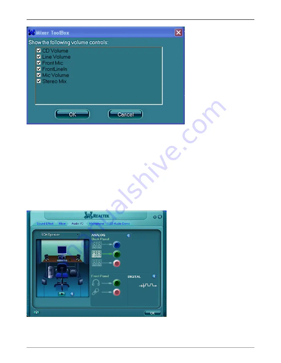
Audio I/O
Realtek HD Audio Manager frees you from default speaker settings. Different from
before, for each jack, they are not limited to perform certain functions. Instead, now
each jack is able to be chosen to perform either output (i.e. playback) function or input
(i.e. Recording) function, we call this “Retasking”.
Audio I/O aims to help you setting jacks as you wish. Moreover, other than blue to blue,
pink to pink, the way that you used to do, Audio I/O would guide you to other right jacks
that can also serve as microphone / speaker / headphone.
Содержание IONITX-E series
Страница 1: ......
Страница 28: ...27 Installing Drivers and Software...
Страница 29: ...28 IONITX Synergy Series Motherboard...
Страница 30: ...29 Installing Drivers and Software 3 Follow the below for HDA sound driver installing...
Страница 31: ...30 IONITX Synergy Series Motherboard 4 Follow the below for Nvidia HDMI Audio driver installing...
Страница 32: ...31 Installing Drivers and Software 5 Follow the below for Wireless LAN driver installing...
Страница 50: ......


