background image


19    

Hardware Installation
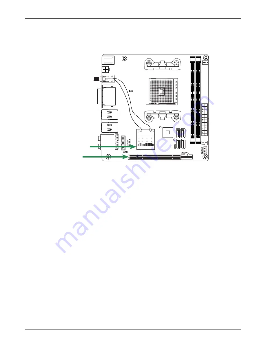
Expansion Slots

The motherboard contains two expansion slots: one PCI Express x16 slot and one 
Mini PCI Express slot. 

Mini PCI Express Slot-MINI_PCIE1

There is one Mini PCIe slot, reserved for the WiFi Module.

PCI Express x16 Slot-PCIEX16

There is one PCIe x16 slot reserved for graphics card. It is fully compliant with PCI 
Express 2.0 specification. 

.

.

.

120

240

121

120

240

121

1.5V

1.5V

MINI_PCIE1
PCIEX16

Содержание A75ITX series

Страница 1: ......

Страница 2: ...CONNECT THE EQUIPMENT INTO AN OUTLET ON A CIRCUIT DIFFERENT FROM THAT OF THE RECEIVER CONSULT THE DEALER OR AN EXPERIENCED AUDIO TELEVISION TECHNICIAN NOTE Connecting this device to peripheral devices...

Страница 3: ...in ATX 12V Power Connector 14 USB Headers 15 FP Audio Header 16 COM Header 16 Front Panel Header 17 Speaker Header 17 Connecting Serial ATA Cables optional 18 Fan Connectors 18 SPDIF Out Connector 18...

Страница 4: ...Defaults 29 Restore User Defaults 29 Launch EFI Shell from filesystem device 29 Flash Update Procedure 30 Installing Drivers and Software 31 Drivers Installation 31 Realtek HD Audio Driver Setup 39 Ge...

Страница 5: ...nd play v Two USB 2 0 ports two via the USB brackets connected to the internal USB header optional v Supports wake up from S1 v Supports USB 2 0 protocol up to 480 Mbps transmission rate q USB 3 0 Por...

Страница 6: ...v Low power consumption and power management features q Green Function v Supports ACPI Advanced Configuration and Power Interface v Suspend to DRAM supported STR v RTC timer to power on the system v A...

Страница 7: ...12 13 PWR2 SW1 JP2 18 20 CPUFAN 4 8 JP1 FP_USB3_1 14 15 17 FP_USB1 1 CPU Fan Connector 2 24 pinATX Power Connector 3 SYS Fan Connector 4 Front Pannel Header 5 Speaker Header 6 SATA Connectors 7 Clear...

Страница 8: ...el Blue Line In Line In Line In Side Speaker Out Green Line Out Front Speaker Out Front Speaker Out Front Speaker Out Pink Mic In Mic In Mic In Mic In Black Center Subwoofer Center Subwoofer Orange Re...

Страница 9: ...stall the WiFi antennas to the WiFi antenna connectors and make sure the screws are rotated in clockwise direction Note 1 Users please note that the appearance of your WiFi antenna modules may not be...

Страница 10: ...Motherboard into the Chassis q Connecting cables and setting switches Safety Instructions To reduce the risk of fire electric shock and injury always follow basic safety precations Remember to remove...

Страница 11: ...ket and can not be seen Please note that any deviation from the correct installation procedures may cause permanent damage to your motherboard 4 Press the CPU down firmly into the socket and close the...

Страница 12: ...ots Refer to the following recommendations to install the memory modules Note that a memory module has a notch so it can only fit in one direction Refer to the following procedure to install memory mo...

Страница 13: ...m dust and foreign objects and promotes correct airflow within the chassis Before installing the motherboard install the I O shield from the inside of the chassis Press the I O shield into place and m...

Страница 14: ...er Connectors v 24 pin ATX Power Connector v 4 pin ATX_12V Power Connector q Internal Headers Connectors v USB Headers v Front Pannel Audio Header v COM Header v Front Panel Header v Speaker Header v...

Страница 15: ...er supply connector Make sure that the power supply cable and pins are properly aligned with the connector on the motherboard Firmly plug the power supply cable into the connector and make sure it is...

Страница 16: ...the bracket to either the front or rear panel of your chassis not all chassis are equipped with the front panel option FP_USB1 Pin Definition PIN Assignment PIN Assignment 1 VCC 2 VCC 3 USBP0 4 USBP1...

Страница 17: ...pin assignment on the cable is the same as the pin assignment on the mainboard header To find out if the chassis you are buying supports a front audio connector please contract your dealer FP_AUDIO1...

Страница 18: ...tach the hard disk drive indicator LED cable to these two pins The HDD indicator LED indicates the activity status of the hard disks q RST SW Attach the Reset switch cable from the front panel of the...

Страница 19: ...herboard SATA Pin Definition Pin Signal 1 GND 2 TXP 3 TXN 4 GND 5 RXN 6 RXP 7 GND Fan Connectors There are two fan connectors on the motherboard The fan speed can be detected and viewed in the PC Heal...

Страница 20: ...nd one Mini PCI Express slot Mini PCI Express Slot MINI_PCIE1 There is one Mini PCIe slot reserved for the WiFi Module PCI Express x16 Slot PCIEX16 There is one PCIe x16 slot reserved for graphics car...

Страница 21: ...JP1 Selection 1 2 Normal 2 3 Clear CMOS 1 1 If you want to clear the system configuration use the JP1 Clear CMOS Jumper to clear data Close Open Default setting Jumper Settings This chapter explains h...

Страница 22: ...Del takes you to the BIOS Setup Utility Note 1 We reserve the right to update the BIOS version presented in the manual The BIOS pictures shown in this section are for reference only 2 It is strongly...

Страница 23: ...in this menu show the PCI related information Press enter to display the configuration options q PCI ROM Priority Allows you to select the PCI Option ROM to launch including Legacy and EFI Compatible...

Страница 24: ...urces q Deep Sleep ErP Compliant When enabled wake up from S4 S5 can only be done by power button q Restore on AC Power Loss This item allows you to configure how the system board responds to a power...

Страница 25: ...tion The items in this menu allow you to change the USB related features Press enter To display the configuration options q Legacy USB Support Allows you to enable or disable support for USB devices o...

Страница 26: ...nter to display the sub menu Display Configuration The items allow you to configure display features including IOMMU Mode and Primary Video Device Memory Configuration The items allow you to configure...

Страница 27: ...se this item to select the keyboard NumLock state On or Off q Fullscreen LOGO Show Enable or disable fullscreen LOGO show q Fast Boot Enable or disable boot with initialization of a minimal set of dev...

Страница 28: ...ssword 1 Select the item Administrator User Password and press Enter 2 From the password box type a password composed of at least six letters and or numbers then press Enter 3 Confirm the password whe...

Страница 29: ...allows you to set the CPUFAN mode Save Changes and Exit Select this item and press Enter to save the changes that you have made in the BIOS Setup and exit the BIOS Setup When the diolog box Save confi...

Страница 30: ...Setup and exit the BIOS Setup When the diolog box Save configuration appears select Yes to save changes or select No to return to the main menu Discard Changes This option allows you to discard the se...

Страница 31: ...ined or downloaded and the utility program EFUDOS exe to the diskette 2 Allow the PC system to boot from the DOS diskette 3 At the DOS prompt type EFUDOS XX ROM P B R N X ENTER Note XX the BIOS file n...

Страница 32: ...ted in the manual The driver installation pictures shown in this section are for reference only 3 To ensure a successful installation please install Microsoft net framework 2 0 or Windows XP SP3 or la...

Страница 33: ...32 AMD A75ITX series motherboard...

Страница 34: ...33 Installing Drivers and Software 3 Left click Realtek HD Audio driver and follow the instructions below to install the sound driver...

Страница 35: ...34 AMD A75ITX series motherboard 4 Left click Realtek network driver and follow the instructions below to install the network driver...

Страница 36: ...35 Installing Drivers and Software 5 Left click Azurewave WIFI driver and follow the instructions below to install the wireless driver...

Страница 37: ...36 AMD A75ITX series motherboard...

Страница 38: ...37 Installing Drivers and Software...

Страница 39: ...38 AMD A75ITX series motherboard 6 At last you can enter Device Manager interface that provides information about the hardware devices on this motherboard and check if the installation is finished...

Страница 40: ...pear Sound Effect After clicking on the Sound Effect tab 3 sections Environment Equalizer and Karaoke are available for selection Environment Simulation You will be able to enjoy different sound exper...

Страница 41: ...ly used for your quick enjoyment How to Use Other than the buttons Pop Live Club Rock shown on the page to pull down the arrow in Others you will find more optimized settings available to you Karaoke...

Страница 42: ...o you to create your favorite sound effect in one single tool Playback control Mute You may choose to mute single or multiple volume controls or to completely mute sound output Tool Show the following...

Страница 43: ...mute single or multiple volume controls or to completely mute sound input Tool Show the following volume controls This is to let you freely decide which volume control items to be displayed Advanced c...

Страница 44: ...in functions Instead now each jack is able to be chosen to perform either output i e playback function or input i e Recording function we call this Retasking Audio I O aims to help you setting jacks a...

Страница 45: ...any available jack Step 2 Dialogue Connected device will pop up for your selection Please select the device you are trying to plug in If the device is being plugged into the correct jack you will be a...

Страница 46: ...o called AC 97 jacks If so please check this item to disable front panel jack detection Enable auto popup dialogue when device has been plugged in Once this item checked the dialog Connected device wo...

Страница 47: ...commended while playing HD Audio Output Source Output digital audio source The digital audio format such as wav mp3 midi etc will come out through S PDIF Out Speaker Calibration After you have success...

Страница 48: ...You will get the best quality if you chose 90 position which we recommend you to use this effectively means that you speak right into the microphone Note A Stereo Microphone is required when using Be...

Страница 49: ...io Demo The section 3D Audio Demo grants you another possibility to enjoy your sound The Audio Demo allows you to listen to sound in an extraordinary way Information This section provides information...

Страница 50: ...r then press Delete to enter BIOS SETUP UTILITY 2 Use the arrow key to select Advanced menu When enter the Advanced menu select the Item IDE SATA Configuration 3 Press Enter to display IDE SATA Config...

Страница 51: ...the option RAID 5 Enable the disks that you want to use as RAID disks 6 Press F10 to save the configuration and exit The PC reboots 7 Enter the RAID BIOS Setup by pressing F10 when prompted and procee...

Страница 52: ...Mode field use the space bar to select a RAID Mode The supported RAID modes include Mirroring RAID 1 Striping RAID 0 and Stripe Mirroring RAID 10 The following is an example of RAID 0 array creation...

Страница 53: ...se the space bar to select Y and press Ctrl Y 3 Enter the LD name 4 ModifyArray Capacity and press Ctrl Y to save the modification When the setup is finished press Esc to exit the RAID interface After...

Страница 54: ...53 SATA RAID User Manual 2 Press Ctrl Y to delete the RAID or press any other key to abort Deleting a RAID set 1 In Main Menu select 3 to enter Delete LD Menu and select the RAID you want to delete...

Страница 55: ...plete the RAID BIOS setup boot from the windowsXP disk The Windows Setup program starts 2 Press F6 and wait a few moments for the Windows Setup screen to appear 3 Specify the AMD drivers a Insert the...

Страница 56: ...55 SATA RAID User Manual b When the window below display press S to use the driver on floppy c Press Enter to continue the windows setup...

Страница 57: ...56 AMD A75ITX series motherboard 291 MA199 00...

Страница 58: ......

Отзывы: