background image

2

Introduction

Welcome to Zoombak ZB100/ZB101 series vehicle installation manual.  
This manual will guide you through the steps required to successfully 
install your locator device in your vehicle.

General Safety

This installation manual covers the installation of the ZB100/ZB101 
series locator devices and should be used to ensure a safe and 
functional locator device installation.  This equipment generates, uses 
and can radiate Radio Frequency (RF) energy, if not installed and used 
in accordance with the instructions may cause harmful interference to 
radio communications

1

zoombak.com

Содержание ZMBK200

Страница 1: ...Zoombak Advanced GPS Car Family Locator Installation Guide z ...

Страница 2: ...assertions of capability included herein are estimates based on limited information gathered from past experience CONFIDENTIALITY This document and the information contained herein are the proprietary and confidential information of Zoombak The information is provided under nondisclosure agreement or other agreement containing disclosure restrictions and may not be reproduced or used for purposes ...

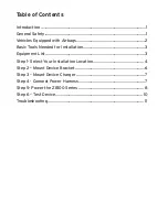
Страница 3: ...h Airbags 2 Basic Tools Needed for Installation 3 Equipment List 3 Step 1 Select Your Installation Location 4 Step 2 Mount Device Bracket 6 Step 3 Mount Device Charger 7 Step 4 Connect Power Harness 7 Step 5 Power the ZB100 Series 8 Step 6 Test Device 10 Troubleshooting 11 ...

Страница 4: ...icle General Safety This installation manual covers the installation of the ZB100 ZB101 series locator devices and should be used to ensure a safe and functional locator device installation This equipment generates uses and can radiate Radio Frequency RF energy if not installed and used in accordance with the instructions may cause harmful interference to radio communications 1 zoombak com ...

Страница 5: ...ause serious injury Airbag wiring is generally marked by use of a Yellow plug Yellow wire loom Yellow tape and or yellow tag The installer must use caution to identify any airbag wiring and avoid cutting testing or tapping into Airbag wiring Failure to comply may cause airbag to inflate this could cause serious injury Contact vehicle manufacturer s corporate headquarters for specific airbag inform...

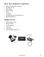
Страница 6: ... socket set Screwdriver set Wire cutters Wire strippers Pliers Flashlight Cordless drill with assorted bit set Digital Multimeter Equipment List ZB100 Series Device Plastic Holster 12v DC Charger 4 zip ties 1 Velcro set 2 piece double sided tape 3 zoombak com ...

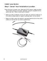
Страница 7: ...securely fastened using the supplied Velcro and or zip ties When mounting the module Make sure the positioning of the unit does not interfere with any of the vehicle components or impede safe operation of the vehicle Make sure that when the vehicle is reassembled that all of the unit s cables are secure and can not be pulled loose 4 zoombak com 3 ...

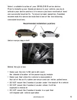
Страница 8: ...wo following concealed locations Under rear package shelf Behind the glove box Make sure the mini USB cable will reach the intended location of the power supply module Make sure that when the vehicle is reassembled that all of the unit s cables are secure and can not be pulled loose DO NOT mount the Zoombak Locator under the hood of the vehicle DO NOT mount the Zoombak Locator where it will be exp...

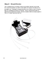
Страница 9: ...allation as well as the ability to remove the device for portable use Zoombak recommends the use of Velcro set or 2 sided tape for installation of device bracket Use of mounting bracket is optional the Zoombak locator can be mounted directly using supplied Velcro 2 sided tape and zip ties 6 zoombak com 5 ...

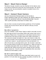
Страница 10: ...xisting factory bolt using crimp on ring connector Please note the power wire is also black however it has a dotted white line with the white plastic fuse holder attached to it This connection should be made first Use a wire brush or rotary file to remove the paint from around the bolt to allow for the best possible connection to ground A good location to find a suitable bolt is in either the driv...

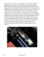
Страница 11: ...s from the point you have obtained power The included fuse is designed to protect the power supply itself Use caution if you are using a fuse tap severe and costly damage may occur to fuse box if they are not used correctly Make certain the circuit you tap into does not fall asleep after the car ignition has been turned off Most new vehicles incorporate battery saver circuits which switch off powe...

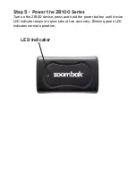
Страница 12: ...ep 5 Power the ZB100 Series Turn on the ZB100 device press and hold the power button until device LED indicator begins to glow about two seconds Blinking green LED indicates normal operation LED Indicator ...

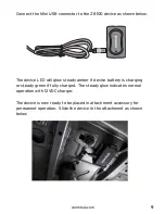
Страница 13: ...ow steady amber if device battery is charging or steady green if fully charged The steady glow indicates normal operation with 12VDC charger The device is now ready to be placed in attachment accessory for permanent operation Slide the device in the attachment as shown below 9 zoombak com ...

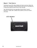
Страница 14: ...evice LED will display a solid amber light when device is charging and a solid green indicator when device is fully charged Your Zoombak device is now operational and ready for service activation Please refer to Quick Start guide for service activation and usage 10 zoombak com LED Indicator ...

Страница 15: ...s 12 volts on the red wire Ensure the USB cable is plugged into ZB100 device Device LED will have Solid Amber or Green light when proper power source has been installed Unable to acquire GPS fix through Web Portal Move the vehicle to new location that does not have obstacles directly overhead Unable to acquire GPS fix through Web Portal Aftermarket window tinting may affect reception of GPS signal...

Отзывы: