5
© Copyright 2020 Zoeller
®
Co. All rights reserved.
HAZARDOUS LOCATION PUMP DESCRIPTION
1. Pumps are constructed of class 30 cast iron with powder coated
epoxy protection for long life when pumping sewage in submersible
applications.
2. Pump motors are available in single and three phase design.
3. The Hazardous Location Pump is a single seal design and has seal
leak probes. Single phase units have an internal thermal overload.
Three phase pumps have a thermal sensor. A moisture sensor
seal fail circuit is incorporated into the control panel required for
nonautomatic pumps. Moisture sensor indicator panel, 10-1031, is
recommended but not required for automatic pump models.
4. Three phase pumps require overload protection in the control panel.
5.
These pumps are to be repaired by firms approved by
Zoeller Company and in accordance to Policy # FM0212-3d. Otherwise,
they are to be returned to the factory for repair.
Note: cCSAus listed pumps are certified to CSA standard C22.2 No 145
and tested to FM standards 3600, 3615 and 3616 by CSA.
FIELD ASSEMBLED INSTALLATION
1. Contractor shall furnish all labor, material, equipment and
incidentals required for installation of hazardous location pump.
2. Installation and piping instructions are included with the rail system
and basin instructions. If pump is being retrofitted to an existing
rail system, accessory parts may be required. Consult the factory
and advise make and model of rail system being used.
3. All electrical connections including pump to control box and power
supply to control panels must comply with the “National Electrical
Code” and applicable local codes. Installation of electrical panels
and connections should be made by a qualified licensed electrician.
4. When installing a pump with a check valve, or a rail system with a
check valve, you must give the pump case time to fill to help prevent
air lock when lowering the unit into the liquid. The 6404/6405 pump
case has an air vent located behind the discharge. This air vent is
across the pump housing mounting surface and must be cleaned
before each reinstall. An air vent hole (3/16") must be drilled in
discharge pipe below the check valve to help prevent air lock.
This drilled hole must be cleaned before each reinstall. After the
pump is installed, run the unit submerged to assure the pump case
is filled (Water should come out of 3/16" diameter hole).
GENERAL INFORMATION
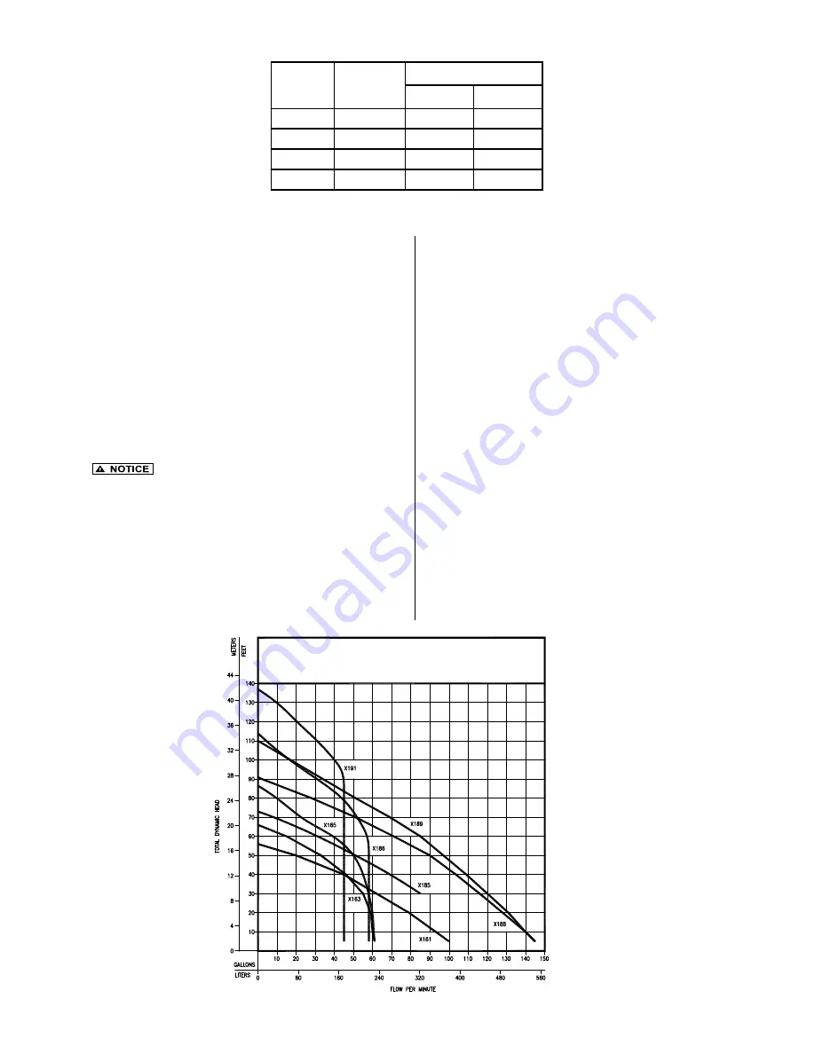
PUMP PERFORMANCE CURVE
MODEL X161/X163/X165/X185/X186/X188/X189
3/4” SOLIDS CAPACITY; X191 5/8” SOLIDS CAPACITY
010740
AWG
ohms/ft
Added resistance
25'
50'
18
0.0064
0.16
0.32
16
0.0040
0.10
0.20
14
0.0025
0.06
0.13
12
0.0016
0.04
0.08
Resistance per foot of power cable


