background image

EVAC reserves the right to make alterations to this specification without  prior notice.
© Copyright Evac Oy. All rights reserved.

1

EVAC

Commercial Marine Equipment

V

V

V

V

VA

A

A

A

ACUUM 

CUUM 

CUUM 

CUUM 

CUUM  T

T

T

T

TOILET

OILET

OILET

OILET

OILET

OPERATION AND MAINTENANCE

Date:

Doc.

23 Aug 2005

3:01025C

5775500

CONTROL MECHANISM, EVAC 90, SQUATTING TOILET

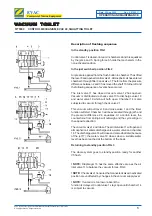
Description of flushing sequence

In the standby position FIG.1

Control valve 1 is closed. Vacuum in chambers 2 and 3 is equalized
by the jets 4 and 5. Spring force 6 holds the mechanism in the
non-activated position.

In the just switched position FIG.2

Air pressure applied from the flush button to chamber 7 has lifted
the lever 8 and opened control valve 1. Atmospheric air has entered
chamber 3 through filter 9 and valve 1. The force from the pressure
difference between 2 and 3 has moved the shaft 10 to the left and
the following sequence of events has occured:

The inlet valve 11 has closed. Vacuum valve 12 has opened.
Vacuum is distributed via check valve 13 to discharge valve 18
and water valve 19 which will both open. Chamber 14 is also
subjected to vacuum through check valve 21.

This vacuum will pull lever 8 and close valve 1 and the timer
function will start. Chamber 3 will be evacuated through jet 5 and
the pressure difference 2-3 equalizes. At a certain level, the
counterforce from spring 6 will outweigh and the cycle will go in
the opposite direction:

The vacuum valve 12 will close. The air inlet valve 11 will open and
atmospheric air enters discharge valve, water valve and chamber
14. The discharge valve 18 will close and somewhat later (because
of the jet 17), the water valve 19 closes when a suitable water
level has been reached at the bottom of the bowl.

Returning to standby position FIG. 3

The whole system goes to standby position ready for another
VT-flush.

! NOTE:

 Diaphragm 16 has the same effective area as the air

inlet valve 11 to balance the vacuum forces. FIG.3

! NOTE:

  Check valve 13 ensures that connected valves in activated

position are unaffected by changes in the vacuum supply level.

! NOTE: 

 If vacuum is too low or absent the

function is delayed. Control valve 1 stays open until chamber 14
is subject to vacuum.

Содержание 5979301

Страница 1: ...ng data Water pressure 200 600kPa Recomended water pressure 250 350kPa Operating vacuum 30 50kPa Water consumption 1 5 2 5 litres flush adjustable Air consumption 60 10 litres flush normal atmospheric...

Страница 2: ...rcial Marine Equipment V V V V VA A A A ACUUM CUUM CUUM CUUM CUUM T T T T TOILET OILET OILET OILET OILET TECHNICALDATA Date Doc 28 Jan 2005 1 01199A 5900200 PNEUMATIC PUSH BUTTON EVAC 90 SQUATTING TOI...

Страница 3: ...360 Different positions can be used Straight connection tube can be used instead of elbow Connection upwards shown only as an example 700 Tiling Floor Water connection Flushingwaterconnection R 1 2 BS...

Страница 4: ...ET INSTALLATION Date Doc 25 Jan 2005 2 01016B 5900200 PNEUMATIC PUSH BUTTON EVAC 90 SQUATTING TOILET Put the slide guide tap to the groove on a cover Snap on the cover and the push button Slide guide...

Страница 5: ...water valve opens and lets rinsing water into the squatting bowl through a hose nipple After a short delay the vacuum acts in discharge valve housing and forces the rubber diaphragm in discharge valv...

Страница 6: ...check valve 13 to discharge valve 18 and water valve 19 which will both open Chamber 14 is also subjected to vacuum through check valve 21 This vacuum will pull lever 8 and close valve 1 and the time...

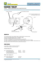
Страница 7: ...1025C pos 4 counters the effect of quick changes in the vacuum supply Jet 3 doc 3 01025C pos 15 delays the vacuum changes in chamber 14 see doc 3 01025C This prevents a new flushing procedure to start...

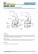
Страница 8: ...Vacuum hose Controlmechanism Operation Closed condition In the closed position the control valve shuts off the connection between the vacuum piping and the discharge valve housing As the valve housin...

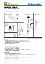
Страница 9: ...Water valve filter 5774150 Clean Control mechanism air filter 5778600 Check operation push button seat and cover rinse pattern discharge pattern Check possible water and vacuum leakage Every 10 years...

Страница 10: ...tion Bowl clogged or discharge valve not operating Misuse buckets of water thrown in the bowl Too low vacuum less than 30 to flush No vacuum or low vacuum less than 30kPa Clogged mini check valve No i...

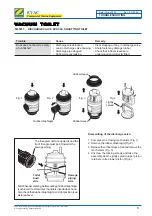
Страница 11: ...tedasshown Alsocheckthatrubberdiaphragmisinrightposition see pictureabove Fig 2 Fig 1 Fig 4 Fig 3 Rubbersleeve Rubbersleeve Rubberdiaphragm Lightly spread Dismantling of the discharge valve 1 Compress...

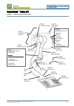
Страница 12: ...ingpan 6542811 DISCHARGEVALVE ASSEMBLY 6543029 Recommended spare part kit 1 x 5435169 Rubberdiaphragm 2 x 5435181 Rubbersleeve 5990210 Hose clamp 5935503 Hose 5990210 Hose clamp 5778992 Water hose 543...

Страница 13: ...for this jet available 5778000Jetcarriercomplete 5778002Jetcarriercomplete 5778004Jetcarriercomplete 5778600 Air filter Jet Carrier identification P N Colour Size Effect 5778004 Yellow 0 20 Extra lon...

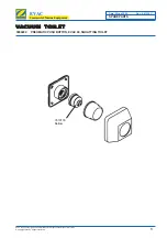
Страница 14: ...notice CopyrightEvacOy Allrightsreserved 1 EVAC Commercial Marine Equipment V V V V VA A A A ACUUM CUUM CUUM CUUM CUUM T T T T TOILET OILET OILET OILET OILET SPARE PARTS Date Doc 25 Jan 2005 6 01030C...

Отзывы: