ZMC464 Motion Controller User Manual V1.5
→
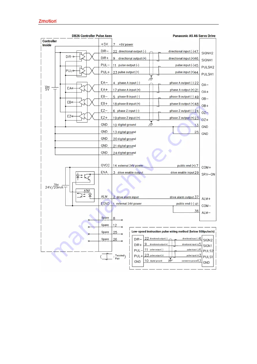
Wiring Note:
The wiring principle of the differential pulse axis interface is shown in the figure
above, and the wiring methods of different types of drivers are different, please
connect carefully.
Страница 1: ......
Страница 2: ...e ZMC controller software and the introduction and routine of each command please refer to the ZBASIC software manual Information contained in this manual is only for reference Due to improvements in...
Страница 3: ...ded into Danger and Caution Failure to operate as required may result in moderate injury minor injury or equipment damage Please keep this guide in a safe place for reading when needed and be sure to...
Страница 4: ...t the insulation distance between cables will not be reduced after the cables are installed on the terminal block Notice Avoid metal shavings and wire ends falling into the hardware circuit board duri...
Страница 5: ...1 Power Input 12 3 1 1 Power Specification 12 3 2 RS485 CAN Communication Interface 12 3 2 1 RS485 CAN Communication Specification Wiring 13 3 2 2 Basic Usage Method 15 3 3 RS232 Serial Port 16 3 3 1...
Страница 6: ...ng 33 3 10 2 Basic Usage Method 36 Chapter IV Expansion Module 39 4 1 CAN Bus Expansion 39 4 1 1 CAN Bus Expansion Wiring 39 4 1 2 CAN Bus Expansion Resource Mapping 41 4 2 EtherCAT Bus Expansion 45 4...
Страница 7: ...64 high performance multi axis motion controller can be applied in robots SCARA Delta 6 joints electronic semiconductor equipment testing equipment assembly equipment locking equipment soldering machi...
Страница 8: ...olation helical interpolation and spline interpolation Support electronic cam electronic gear position latch synchronous follow virtual axis and other functions Support hardware comparison output HW_P...
Страница 9: ...ller User Manual V1 5 1 3 System Frame 1 4 Hardware Installment The ZMC464 motion controller is installed horizontally with screws and each controller should be fastened with 4 screws Unit mm Mounting...
Страница 10: ...oid direct sunlight installation In order to facilitate ventilation and controller replacement 2 3cm should be left between the upper and lower parts of the controller and the installation environment...
Страница 11: ...xis interface IO there are 3 inputs and 3 outputs in total in 3 AXIS axis interfaces Max Extended IO 4096 inputs 4096 outputs PWM 4 AD DA 2 general DA 0 10V Max Extended AD DA 1000 ADs 1000 DAs Pulse...
Страница 12: ...tronic cam continuous trajectory motion robot structure ZMC464 16 16 axes point to point linear circular electronic cam continuous trajectory motion robot structure ZMC464 16R Functions of ZMC464 16 D...
Страница 13: ...1 Power state it lights when power is conducted RUN 1 Run state it lights when runs normally ALM 1 Error state it lights when runs incorrectly RS232 RS232 serial port port0 1 Use MODBUS_RTU protocol R...
Страница 14: ...24 NPN type the power is supplied by internal 24V power supply There are 2 high speed inputs and IN0 1 have the latch and encoder function OUT Digital IO output port 12 NPN type the power is supplied...
Страница 15: ...ZMC464 Motion Controller User Manual V1 5 Direction 3 axial direction Shock collide 15g 11ms half sinusoid 3 axial direction Degree of Protection IP20...
Страница 16: ...ntroller Terminal Definition Terminal Name Type Function E 24V Input Positive terminal of DC power input EGND Input Negative terminal of power input FG Earthing Protect 3 1 1 Power Specification Speci...
Страница 17: ...mainly including 485A 485B and public end The CAN interface of the controller adopts the standard CAN communication protocol which mainly includes three ports CANL CANH and the public end And it can...
Страница 18: ...s of the CAN bus communication both parties are connected together In CAN bus left and right sides connect a 120 resistor respectively please see below graphic Wiring Notes As above the daisy chain to...
Страница 19: ...ment grounding chassis on the entire line must be good and the grounding of the chassis should be connected to the standard factory ground pile Cable Requirements Shielded Twisted Pair and the shielde...
Страница 20: ...uipment to match the parameters of each node 6 Correctly set the address and speed of the slave station expansion module according to the manual of the slave station 7 After all the settings are compl...
Страница 21: ...wer and output for the public end 9 E5V Output Positive pole output of 5V power maximum is 300mA 3 3 1 RS232 Communication Interface Specification Wiring Specification Item RS232 Maximum Communication...
Страница 22: ...o connect the public ends of each communication node to prevent the communication chip from burning out Please use STP especially in bad environments and make sure the shielding layer is fully grounde...
Страница 23: ...o their respectively instructions correctly set the relevant parameters of the third party equipment to match the parameters of each node 5 When all is configured it can start to do communicating 6 Co...
Страница 24: ...ground EGND IN8 NPN leakage type low speed input Input 8 IN9 Input 9 IN10 Input 10 IN11 Input 11 IN12 Input 12 IN13 Input 13 IN14 Input 14 IN15 Input 15 EGND External power ground EGND IN16 NPN leakag...
Страница 25: ...7V Minimal current 2 3mA negative 1 8mA negative Max current 7 5mA negative 6mA negative Isolation mode optoelectronic isolation Note the above parameters are standard values when the voltage of cont...
Страница 26: ...ed 3 4 2 Basic Usage Method 1 Please follow the above wiring instructions to wiring correctly 2 After powered on please select any one interface among the three interfaces ETHERNET RS232 and RS485 to...
Страница 27: ...GND External power ground E5V External 5V power output max is 300mA OUT0 NPN Leakage type high speed output Output 0 PWM 0 Hardware Comparison Output PUL4 OUT1 Output 1 PWM 1 DIR4 OUT2 Output 2 PWM 2...
Страница 28: ...Frequency 400kHz 8kHz Voltage level DC24V DC24V Max output current 300mA 300mA Max leakage current when off 25 A 25 A Respond time to conduct 1 s resistive load typical value 12 s Respond time to clos...
Страница 29: ...ernal input device If the DC power supply of the external device and the controller power supply are in the same power supply system this connection can also be omitted The E5V port is a 5V power outp...
Страница 30: ...hrough HW_PSWITCH2 Please refer to ZBasic for details 3 6 DA Analog Output The analog port adopts a set of 5Pin screw type pluggable terminals with a spacing of 3 81mm Terminal Definition Terminal Nam...
Страница 31: ...ance 10K Wiring Reference Wiring Note The analog input output wiring method is as shown in the figure above and the external load signal range must match with this signal range Please use STP especial...
Страница 32: ...read through AIN command and corresponding analog voltage can be output through AOUT command also data of each channel can be checked through ZDevelop View AD DA Please refer to ZBasic for details 3 7...
Страница 33: ...lt IP address is 192 168 0 11 The pin definition is as follows The Ethernet port of the controller can be connected to a computer HMI etc through an Ethernet cable and using point to point connection...
Страница 34: ...5 3 9 EtherCAT Bus Interface ZMC464 motion controller has a 100M EtherCAT communication interface and it supports EtherCAT protocol In addition EtherCAT driver or EtherCAT expansion module can be con...
Страница 35: ...data Maximum 1486 bytes of one single frame Synchronization shaking of two slave stations 1us Refresh 1000 digital input and output about is 30us 16 servo axes is about 100us Communication Cable Requi...
Страница 36: ...insulated terminals and cables with appropriate wire diameters to connect the user terminals 3 10 AXIS Differential Pulse Axis Interface This product provides 3 local differential pulse axis interfac...
Страница 37: ...al B 19 EZ Encoder differential input signal Z 20 GND Negative pole of 5V power of pulse encoder signal 21 GND 22 DIR Servo or step direction output 23 PUL Servo or step pulse output 24 GND Negative p...
Страница 38: ...evel DC24V The voltage to open 10 5V The voltage to close 10 7V Minimal current 1 8mA negative Maximum current 4mA negative Isolation optoelectronic isolation OUT12 14 Output method NPN leak type it i...
Страница 39: ...roller User Manual V1 5 Wiring Note The wiring principle of the differential pulse axis interface is shown in the figure above and the wiring methods of different types of drivers are different please...
Страница 40: ...among the three interfaces ETHERNET RS232 default parameter it can be connected directly and RS485 default parameters it can be connected directly but for hardware adapter head is needed to connect t...
Страница 41: ...ZMC464 Motion Controller User Manual V1 5 5 Control corresponding motion through View Manual Refer to BASIC Routine...
Страница 42: ...SPEED 10 10 set axis speed as 10 1000 pulse s ACCEL 1000 1000 set axis acceleration as 1000 1000 pulse s s FWD_IN 1 1 prohibit using axis positive hardware position limit REV_IN 1 1 prohibit using ax...
Страница 43: ...to connect one 120 ohm resistor externally When connecting multiple CAN expansion modules you only need to dial ON for the eighth digit of the last expansion module which means please do not dial bit...
Страница 44: ...e one power When they use different power supplies controller power EGND needs to connect to expansion module power GND otherwise CAN may be burnt out When connecting multiple ZIO expansion modules on...
Страница 45: ...nvalid It needs to be powered on again to take effect Dial 1 4 to select the CAN address and the controller sets the IO number range of the corresponding expansion module according to the CAN DIP addr...
Страница 46: ...number in IN and OP must include IO point in the axis interface use the bit 1 4 to set the ID so as to determine the number range of IO to be expanded If the controller itself contains 28 INs and 16...
Страница 47: ...s of 4 The allocation of digital IO numbers corresponding to different dial code IDs is as follows DIP 1 4 combination value Starting AD number End AD number Starting DA number End DA number 0 8 15 4...
Страница 48: ...al axis AXIS_ADDRESS 6 1 32 0 ZCAN expansion module ID 1 axis 0 is mapped to axis 6 ATYPE 6 8 ZCAN extended axis type pulse direction stepping or servo UNITS 6 100 0 pulse equivalent 1000 SPEED 6 100...
Страница 49: ...in this way it supports IO remote expansion 4 2 1 EtherCAT Bus Expansion Wiring After the expansion wiring is completed each EIO expansion module does not need to develop again It only needs to manua...
Страница 50: ...equence of the devices on the bus You can view the total number of devices connected to the bus through the NODE_COUNT slot command Drive number The controller will automatically identify the drive on...
Страница 51: ...multiple of 8 Example NODE_IO 0 0 32 set the IO start number of slot 0 interface device 0 to 32 If device 0 is EIO16084 after configuration according to the above syntax the IO numbers corresponding t...
Страница 52: ...erCAT bus drive number 0 bound as axis 0 AXIS_ADDRESS 1 0 16 1 1 the second drive on the EtherCAT bus drive number 1 bound as axis 1 If the first node is EIO16084 and EIO16084 is connected to drive th...
Страница 53: ...troller program quickly develop applications diagnose system operating parameters in real time and watch the motion controller The running program is debugged in real time and supports Chinese and Eng...
Страница 54: ...ZMC464 Motion Controller User Manual V1 5 2 Click File New File select file type to build here select Basic click OK 3 Double click AutoRun enter task number 0...
Страница 55: ...asic file will be saved under zpj project automatically Save all means all files under this project will be saved 5 Click controller connect if no controller select connect to simulator Then connect t...
Страница 56: ...download RAM download ROM if it is successful there is print indication at the same time program is downloaded into controller and runs automatically RAM it will not save when power off ROM it will s...
Страница 57: ...nt 8 Click View Scope to open oscilloscope Note When opening an project choose to open the zpj file of the project If only the Bas file is opened the program cannot be downloaded to the controller Whe...
Страница 58: ...ws linux Mac Android and wince and provides dll libraries in various environments such as vc c vb net and labview as shown in the figure below PC software programming refers to ZMotion PC Function Lib...
Страница 59: ...asic box click next or finish 4 Find C function library provided by manufacturer Routine is below 64 bit library 5 Copy all DLL related library files under the above path to the newly created project...
Страница 60: ...lib Related header files zauxdll2 h zmotion h Item 2 Add static libraries and related header files in sequence in the pop up window 7 Declare the relevant header files and define the controller conne...
Страница 61: ...f the device can be appropriately adjusted according to the surrounding environment to make it work within the specified standard environment Check item Check content Inspection standards power supply...
Страница 62: ...g Whether the cable is damaged aged cracked The cable must not have any abnormal appearance 6 2 Common Problems Problems Suggestions Motor does not rotate 1 Check whether the ATYPE of the controller i...
Страница 63: ...O board POWER led is ON RUN led is OFF 1 Check whether the power of the power supply is sufficient At this time it is best to supply power to the controller alone and restart the controller after adju...
Страница 64: ...n be checked and captured after connection through serial port 3 When net port led is off please check wiring 4 Check whether controller power led POWER and running indicator led RUN are ON normally 5...