background image

ZMC420SCAN Motion Controller 


15 


description.


Содержание ZMC420SCAN

Страница 1: ...ZMC420SCAN bus motion controller hardware manual Version 1 0...

Страница 2: ...manual Refer to the ZBASIC software manual for detailed information about the ZMC controller software and the introduction and routines of each instruction The information in this manual is for refer...

Страница 3: ...n Controller 2 machine Please be sure to design an effective safety protection device in the machine and add an error handling program to the software otherwise the loss caused by the company is not o...

Страница 4: ...Input 8 15 9 2 2 4 3 Input 16 23 9 2 2 5 General output 10 2 2 5 1 Output 0 2 10 2 2 5 2 Output 3 11 11 2 2 6 AD DA signal 11 2 2 7 U Disk interface signal 11 2 2 8 Axis interface signal 12 2 2 8 1 Lo...

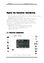
Страница 5: ...linear interpolation arbitrary arc interpolation space arc spiral interpolation electronic cam electronic gear synchronous follow virtual axis settings Etc using optimized network communication proto...

Страница 6: ...rts Ethernet USB CAN 485 and other communication interfaces It can connect various expansion modules through the CAN bus to expand the number of input and output points or motion axes 120 ohm resistor...

Страница 7: ...c library zmotion dll is needed when the program runs 1 3 Features Up to 20 axis motion control 4 pulse axis EtherCAT axis RTEX axis encoder axis galvanometer axis virtual axis Pulse axis output mode...

Страница 8: ...on arbitrary space circular interpolation helical interpolation spline interpolation Support pulse axis bus axis galvanometer axis mixed interpolation Support electronic cam electronic gear position l...

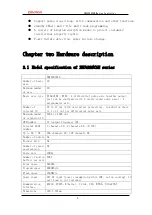
Страница 9: ...ngle ended pulse axes 4 galvanometer axis Number of internal IO 24 in 12 out with overcurrent protection in addition there is 1 in 1 out per differential pulse axis Maximum number of expansion IO 4096...

Страница 10: ...to the encoder of axis 0 3 Axis 4 5 6 7 can be configured as galvanometer axis with ATYPE 21 Single ended pulse axis needs to pass AXIS_ADDRESS is used to force the configuration of the local axis Any...

Страница 11: ...by ATYPE and PWM ZMC4 series supports the function of positive motion XPLC which can be configured and displayed through the network 2 2 ZMC420SCAN wiring ZMC420SCAN has 20 axes up to 32 virtual axes...

Страница 12: ...ort and one for each axis Output port 2 0 10V AD 2 0 10V DA ZMC420SCAN has one RS232 serial port one RS485 and one Ethernet interface ZMC420SCAN has a CAN bus interface that supports connection of exp...

Страница 13: ...MC420SCAN series controllers are powered by a single power supply and ZMC0 2 series and ZIO expansion cards are powered by dual power supplies 5V shaft and encoder interface use internal power supply...

Страница 14: ...nal power ground 4 CANL CAN differential data 5 CANH CAN differential data When multiple controllers are connected on the CAN bus it is necessary to connect 120 ohms in parallel to the CANL and CANH t...

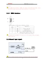
Страница 15: ...2 interface Its 9pin pin is defined as follows Pin number name Explanation 2 RXD Receive data pin 3 TXD Send data pin 5 EGND External power ground 9 E5V External power supply 5V output can be used to...

Страница 16: ...ZMC420SCAN Motion Controller 15 description...

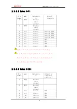
Страница 17: ...er 4 EB7 8 IN5 Enter 5 EZ7 9 IN6 Enter 6 EA8 10 IN7 Enter 7 EB8 Input 0 and input 1 have the function of latching input A and latching input B at the same time Input 2 and input 3 have the function of...

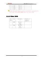
Страница 18: ...10 IN15 Enter 15 Single end encoder shafts 6 9 need to be forcedly configured with a local shaft through AXIS_ADDRESS before they can be used 2 2 4 3 Enter 16 23 Pin number name Explanatio n Default...

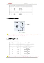
Страница 19: ...circuit There is another universal output port without current amplification in each axis signal see the description of the axis interface 2 2 5 1 Output 0 2 Pin number name Explanation 6 EGND Externa...

Страница 20: ...ZMC420SCAN Motion Controller 19 output Single ended pulse axes 6 11 need to be forced to configure a local axis through AXIS_ADDRESS before they can be used...

Страница 21: ...The PWM output of ZMC420SCAN is controlled by the normal output function Only the output is ON or not can the PWM be actually output which can be used to control the laser energy The output of ZMC420...

Страница 22: ...og output port 0 4 DA1 0 10V analog output 1 5 AGND Internal power supply analog ground ZMC420SCAN internal DA is adoptedInternal power supply 2 2 7 U disk interface signal Pin number name Explanation...

Страница 23: ...Pin number sign al Expl anat ion 1 EGND External power ground 2 IN24 29 ALM Universal input it is recommended to drive alarm 3 OUT12 17 ENABLE General output it is recommended to enable the drive 4 E...

Страница 24: ...Controller 23 14 OVCC External E 24V output Suggestion only IO 15 spare spare 16 spare spare 17 EA Encoder input 18 EB Encoder input 19 EZ Encoder input 20 GND Internal power ground twenty one GND Int...

Страница 25: ...r step direction output twenty three PUL Servo or step pulse output twenty four GND Internal power ground 25 spare spare 26 spare spare 2 2 8 1 Low speed differential pulse port and encoder wiring ref...

Страница 26: ...Motion Controller 25 Encoder connection ZMC420SCAN controller and Panasonic A5 servo drive low speed differential pulse port wiring reference If a high speed differential pulse port or encoder is con...

Страница 27: ...ZMC420SCAN Motion Controller 26 controller 24 pin GND and driver 13 must be connected...

Страница 28: ...e When the speed meets the requirements the low speed differential pulse port is preferentially used When using the high speed differential pulse interface be sure to connect the internal digital grou...

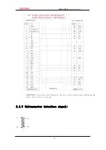
Страница 29: ...ZMC420SCAN Motion Controller 28 ZMC420SCAN controller and Panasonic A5 servo drive high speed differential pulse port wiring reference 2 2 9 Galvanometer interface signal...

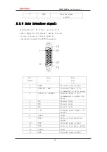
Страница 30: ...us signal 15 GND Digitally Local axis number 4 5 can be configured as the first galvanometer with ATYPE 21 local axis number 6 7 can be configured as the second galvanometer with ATYPE 21 and the axis...

Страница 31: ...power supply and the ZIO expansion card is powered by a dual power supply When used the two channels of the IO board are used The power supply can be connected to a power supply When the ZMC420SCAN c...

Страница 32: ...ut power supply wiring reference Chapter Four common problem prob lem Suggestions for solving problems The motor does not rotate Confirm that the ATYPE configuration of the controller is correct Confi...

Страница 33: ...e drive is working properly and there are no alarms The motor can rotate but the work is not correct Check whether the set deceleration and speed exceed the equipment limit often Check whether the out...

Страница 34: ...ohm resistor is installed at both ends Check if there are multiple expansion modules with the same ID No signal detected at input Check whether the IO power supply is available Check whether the signa...

Страница 35: ...Hardware installation 5 1 ZMC420SCAN installation dimensions Unit mm mounting hole diameter 4 5mm 5 2 Comprehensive wiring reference For expansion boards please refer to ZIO Expansion Card Hardware M...

Отзывы: