M.2CANFD
M.2 Interface CAN (FD) Card
©2022 Guangzhou ZLG Electronics Co., Ltd.
12
User Manual
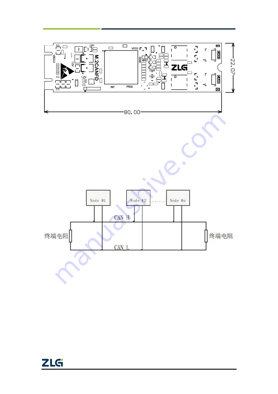
Figure 2.6 Product dimensions
2.8
System Connections
When the M.2CANFD interface card is connected to the CAN-bus bus, it is only
necessary to connect CAN_L to CAN_L and CAN_H to CAN_H signals. The CAN-bus
network adopts a linear topology, and the two terminals of the bus need to be installed
with 120 ohm terminal resistors; if the number of nodes is greater than 2, the intermediate
nodes do not need to install 120 ohm terminal resistors. For branch connections, the
length should not exceed 3 meters. Figure 2.2 shows the CAN-bus connection.
Figure 2.7 Linear topology of CAN-bus network
In the CAN-bus network, shielded wires are often used for interconnection, so as to
enhance the anti-interference ability. However, there are many types of shielded wires and
field wiring is complicated. Therefore, the wiring diagrams of different types of cables in
application are shown below, including the connection diagrams of double-core single-layer
shielded wire, double-core double-layer shielded wire, and three-core single-layer shielded
wire (The "equipment iron shell" in the pictures refers to the outer shell of the device, which
is grounded by default). Regardless of the type of cable, reasonable changes must be
made according to the complexity of the field wiring. Ensure the reliable grounding of the
single point of the shielded wire or ground wire at any time, and carry out on-site wiring in
strict accordance with the wiring specifications to minimize communication errors and
abnormalities, and improve the communication quality and service life of the bus.


