CANDTU-200UWGR
CAN Bus Message Recording and Wireless Data Transmission Equipment User Manual
©2021 Guangzhou ZLG Microelectronics Technology Corp.,Ltd.
12
User Manual
Table 3.13 CAN-Bus Interface Specifications
parameter
Minimu
m
Typical
value
Maximu
m
Unit
Communication baud rate
5k
1M
bps
Number of nodes
110
pcs
Dominant level (logic 0)
CANH
2.75
3.5
4.5
V
CANL
0.5
1.5
2
Recessive level (logic 1)
CANH
2
2.5
3
CANL
2
2.5
3
Differential level
Dominant (logic 0)
1.2
2
3.1
Recessive (logic 1)
-0.5
0
0.05
Maximum withstand
voltage of the bus pin
-18
18
Instantaneous voltage of
the bus
-100
+100
Isolation voltage (DC)
3500
V
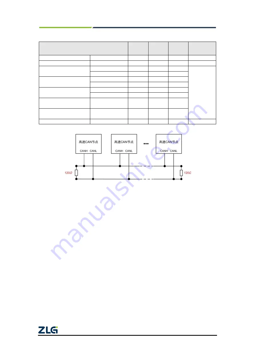
Figure 3. 4 High-speed CAN typical network connection
The CAN bus adopts balanced transmission. ISO11898-2 stipulates: In the
high-speed CAN, a 120 ohm terminal resistor needs to be connected to the network
terminal node to eliminate signal reflection on the bus and avoid signal distortion. Figure
3.4 shows the high-speed CAN network topology.
The device has a built-in 120 ohm terminal resistance, which can be configured to
turn on or off by using the configuration tool CANDTU. For operation details, see 4.2.1.
Note: The bus communication distance and communication rate are related to the field application and
can be designed according to the actual application and related standards. The CAN-Bus cable can use
ordinary twisted pair, shielded twisted pair or standard bus communication cable. In long-distance
communication, the terminal resistance value needs to be selected according to the communication
distance, cable impedance and number of nodes.
3.3.5 LIN-Bus Interface
The device provides one independent LIN-Bus interface. The physical form of the
interface is a flange terminal. Table 3.9, Table 3.10, and Table 3.11 list the interface
diagrams, signal definitions,
See Table 3.14, Table 3.15, and Table 3.16.


