background image


ZK75 Series User Manua

l


29 

The error output for track 1 is "%E?". 

The error output for track 2 is ";E?". 

The error output for track 3 is "+E?". 


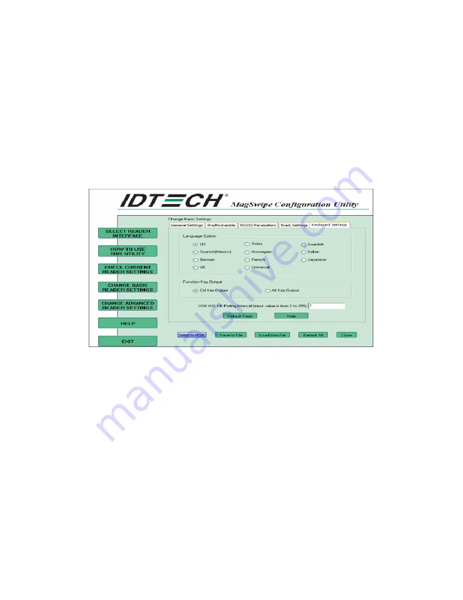
Keyboard Settings 

  There are keybroad settings information on a magnetic stripe. MiniMag II will support following foreign 
language keyboard and function key output for PS/2 and USB HID Keyboard Interface. 


1.


Language Option 

This option allows the user to select the keyboard language of US, Swiss, Swedish, Norwegian, Italian, 
Spanish(Mexico), German, French, Japanese, UK and Universal. Universal language sends out all the data as a 
series of ALT keyped sequence. 


2.


Function Key Output 

The function key output be used to support the special key to delay card data output. 


3.


USB HID KB Polling Interview 

The user can input the number between 1 to 255 for the delay of output. 

4.


Check Current Reader Setting 

Содержание ZK75 Series

Страница 1: ...USER MANUAL ZK75 Series Version 1 1 Date September 2017...

Страница 2: ...t allowed to excerpt copy the content of this manual in part or in full also spread in any form The product described in the manual maybe includes the software which copyrights are shared by the lice...

Страница 3: ...ced in any form or by any means without the prior written permission from ZKTeco Due to the constant renewal of products the company cannot undertake the actual product in consistence with the informa...

Страница 4: ...electrical shock 9 If one of the following situations arises get the equipment checked by a service personnel 10 The power cord or plug is damaged 11 Liquid has penetrated into the equipment 12 The eq...

Страница 5: ...LINE OUT JACK Pin Definition 6 3 5 VGA USB DC12V connector Pin Definition 6 3 6 VGA Pin Definition 7 3 7 LVDS connector Pin Definition 7 3 8 EDP connector Pin Definition 8 3 9 DC Jack Pin Definition...

Страница 6: ...d Reader Configuration Utility 21 5 3 RFID 30 5 3 1 Install driver 30 5 3 2 Install framework 4 0 32 5 3 3 Quick Start with Demonstration Software 33 5 4 Configuration Utility of i Button Reader Insta...

Страница 7: ...K75 Series User Manual 1 1 Packing List 1 1 Standard Accessories a a System with stand b Power Adapter c Power Cord d Driver Bank d 1 2 Optional Accessories a b a Single MSR b VFD c 8 10 2nd Display c...

Страница 8: ...ZK 75 Series User Manual 2 2 System View 2 1 Rear View 2 2 Side View 2 3 Front View Please make sure 19V DC plug in the left righdirection before plugging in DC jack...

Страница 9: ...DDR3L 1333 up to 8GB Storage 2 5 SATAII HDD SSD Audio Line out Network RJ45 10 100 1000 Base T USB port 5 USB 2 0 1 USB 3 0 COM Port 3 RJ45 BIOS Insyde BIOS Power AC 19V 90W Adaptor Thermal Solution F...

Страница 10: ...h TFT LCD LED Backlight 15 6 inch TFT LCD LED Backlight Resolution 1024 768 Pixels 1366 768 Pixels Brightness 350 cd m2 250 cd m2 Touch Panel 5 wire Resistive Type Projected Capacitive Type Note Intel...

Страница 11: ...connector Pin Definition No Definition No Definition 1 5V 5 5v 2 D 6 D 3 D 7 D 4 GND 8 GND 3 2 2 Layer USB3 0 2 0 connector Pin Definition No Definition No Definition 1 5V 8 TX 2 D 9 TX 3 D 10 5V 4 GN...

Страница 12: ...3 MDI1A 4 MDI1A 5 MDI2A 6 MDI2A 7 MDI3A 8 MDI3A 3 4 LINE OUT JACK Pin Definition No Definition 1 GND_AUD 2 GND_AUD 3 LINE_OUTR2 4 LINE_OUTL2 5 LINE2 JD 3 5 VGA USB DC12V connector Pin Definition No De...

Страница 13: ...6 USB D 7 GND 17 12V 8 BLUE 18 USB D 9 GND 19 Reserve for VGA 5V 10 GREEN 20 5V 3 6 VGA Pin Definition No Definition No Definition 1 Red 9 N C 2 Green 10 GND 3 Blue 11 N C 4 N C 12 I2C DATA 5 GND 13 H...

Страница 14: ...0 DATA0 11 GND 12 GND 13 CLK 14 DATA2 15 CLK 16 DATA2 17 GND 18 GND 19 N C 20 DATA3 21 Brightness 22 DATA3 23 BKL enable 24 GND 25 GND 26 GND 27 LED Power 12V 28 LED Power 12V 29 LED Power 12V 30 LED...

Страница 15: ...7 TxD0 22 BKL enable 8 GND 23 Brightness 9 AUX 24 N C 10 AUX 25 N C 11 GND 26 12V 12 3 3V 27 12V 13 3 3V 28 12V 14 N C 29 12V 15 GND 30 N C 3 9 DC Jack Pin Definition No Definition 1 19V 2 Ground 3 1...

Страница 16: ...RST 6 CTS 7 TxD 8 RxD 3 11 SATA 22 pin SATA Pin Definition No Definition No Definition S1 GND P1 N C S2 SATA_TX0_P P2 N C S3 SATA_TX0_N P3 N C S4 GND P4 GND S5 SATA_RX0_N P5 GND S6 SATA_RX0_P P6 GND S...

Страница 17: ...efinition No Definition 1 WAKE 29 GND 2 V3 3V 30 SMB__CLK 3 N C 31 PCIE_TX_N 4 GND 32 SMB_DATA 5 N C 33 PCIE_TX_P 6 1 5V 34 GND 7 CLKREQ 35 GND 8 N C 36 USB D 9 GND 37 N C 10 N C 38 USB D 11 CLK_PCIE_...

Страница 18: ...ND 49 N C 22 RESET 50 GND 23 PCIE_RX_N 51 N C 24 3 3V_AUX 52 V3 3V 25 PCIE_RX_P 53 GND 26 GND 54 GND 27 GND 55 GND 28 V1 5V 56 GND 3 13 Int Speaker Pin Definition No Definition 1 Left Out 2 Left Out 3...

Страница 19: ...V Standby 2 5V Status 3 Power On 4 GND 3 15 NFC port connector Pin Definition No Definition 1 5V 2 USB D 3 USB D 4 GND 3 16 Sideward USB port connector Pin Definition No Definition 1 GND 2 USB D 3 USB...

Страница 20: ...tion 1 5V 2 5V 3 DSR4 4 TxD5 for touch panel 5 DTR4 6 RxD5 for touch panel 7 RTS4 8 GND 9 CTS4 10 12V 11 TxD4 12 5V 13 RxD4 14 3 3V 15 GND 16 GND 17 5V 18 5V Standby 19 USB D 20 5V 21 USB D 22 Power O...

Страница 21: ...ZK75 Series User Manual 15 4 12V 24V 5 N C 6 GND...

Страница 22: ...ies User Manual 16 4 System Assembly Disassembly 4 1 HDD 4 2 Memory Note Unscrew 4 screws and remove the base cover Fasten HDD on HDD bracket with 2 screws Install HDD with 2 screws Put the memory int...

Страница 23: ...with 2 screws 3 Plug MSR cable 4 Install MSR with 2 screws 1 Remove the Top cover 2 Plug VFD display cable 3 Install VFD with 2 screws 4 Cover the Top cover with Hinge hole 1 Remove the Top cover 2 Pl...

Страница 24: ...ule into the Mini PCIE Slot 2 Connect 2 antennas on Wi Fi module Notice The antenna in black should be connected on position 1 of WI FI module and antenna in gray should be connected on position 2 of...

Страница 25: ...Manual 19 5 Device Driver Installation 5 1 Resistive Type Touch Panel and P CAP 1 Click Next 2 Click Next 3 Click Next 4 Select None Click Next 5 Click OK 6 Select Support Multi Monitor System Click N...

Страница 26: ...anual 20 8 Click Next 9 Click Next 10 Select Create a eGalaxTouch Utility shortcut on desktop Click Next 11 Would you do 4 point calibration now Click Yes 12 Do 4 points aligrment to match display 13...

Страница 27: ...to install the Utility program 1 Insert the setup CD 2 Run the 80066804 006_Magswipe_Configuration_Software_V2_1_A setup file that is located in the Software folder of CD 3 Follow the wizard to comple...

Страница 28: ...be connected Select the corresponding connected reader interface and click the Continue button After the interface selection is made click the Continue button The utility attempts to communicate with...

Страница 29: ...tripe Reader MSR configuration process The Basic Reader Settings group defines the basic operating parameters and data output format of the reader Button Definitions 1 Send To MSR When all the setting...

Страница 30: ...at has been previously saved Select this command start a File Open dialog which allows selection of the file 3 Save To File The configuration data can be saved as a file and being used later to config...

Страница 31: ...or off the MSR If MSR is disabled no data is sent out to host in any case The default is MSR Reading Enabled 2 Decoding Method Settings This option gives four kinds of decoding methods Raw Data output...

Страница 32: ...levels or off Four loudness levels are a Quick High b Quick Low c High d Low e The default is High beep 4 Terminal Type a NoteBook b IBM PC AT c IBM PC AT External keyboard d IBM PC AT No External ke...

Страница 33: ...serves the same purpose as the Preamble except the extra characters are added to the end of a data string The Postamble can be added only after a terminator character if specified 3 Track Prefix and...

Страница 34: ...the card will be read 2 Track Separator Selection This option allows the user to select the character to be used to separate data decoded by a multiple track reader The default value is CR 3 Send Star...

Страница 35: ...ID Keyboard Interface 1 Language Option This option allows the user to select the keyboard language of US Swiss Swedish Norwegian Italian Spanish Mexico German French Japanese UK and Universal Univers...

Страница 36: ...e configuration data of the connected reader will be displayed like in the example 5 3 RFID 5 3 1 Install driver 1 Check the Device Manager to verify the status of RFID reader Computer Management Devi...

Страница 37: ...ZK75 Series User Manual 31 3 Select Browse my computer for driver software 4 Click Browse to select file called HFF320U Driver FTD x64 and click Next 5 Install the driver...

Страница 38: ...ZK 75 Series User Manual 32 6 Install complete and then click close 7 Restart the computer 5 3 2 Install framework 4 0 1 Double click to install...

Страница 39: ...art with Demonstration Software 1 The demonstration software is MP Studio exe provided in the folder Demo Software There is no software setup required just double click the MP Studio exe The demonstra...

Страница 40: ...r quick understanding 5 4 Configuration Utility of i Button Reader Installation Below steps guide you how to install the Utility program Insert the setup CD Run the ZKTeco IButton Utility exe setup fi...

Страница 41: ...ZK75 Series User Manual 35...

Страница 42: ...er If detected all the input text boxes will be enabled If the reader has not been connected to PC yet please connect the reader and then click Refresh to get connected Configuration Below is the main...

Страница 43: ...tton data format SS iButton 64 Bit Registration Number ES 1 Length i Button ID length request from 0 16 2 Output order 4 formats could be select at Attach Remove i Button ID iButton 64 Bit Registratio...

Страница 44: ...ZK 75 Series User Manual 38 2 Setup VFDset exe software...

Страница 45: ...s as shown in the above figure the baud rate will show on states page of VFD module Note You may check it when power on VFD module then click Open COM button 7 Get Setting from VFD button to get all t...

Страница 46: ...characters line 2 maximum 20 characters total of 40 characters ASCII mode You can type the character by keyboard 0x20h 0x7Fh if you press clear icon it will clear the all Message characters on AP Hex...

Страница 47: ...splay for enable new setting 9 Click Save button To save user s setting in file for example below picture to save file name as GOODLUCK file set for Welcome Message 10 Click Load button After saving y...

Страница 48: ...Manual 42 6 BIOS Utility setup Press DEL key to enter SETUP CMOS UTILITY when system boot up 1 Please press DEL key tenderly and slowly 2 Please press ENTER over SCU Button key 3 Press F9 to view the...

Страница 49: ...o the Windows Date and Time Properties utility WARNING Setting the wrong values in the sections below may cause the system to malfunction Make sure that the settings made are compatible with the hardw...

Страница 50: ...uration Use the Audio Configuration menu to read Audio configuration information and configure the Audio settings 6 1 3 Video Configuration Use the Video Configuration menu to read Video configuration...

Страница 51: ...User Manual 45 6 1 4 SATA Configuration Use the SATA Configuration menu to read SATA configuration information and configure the SATA settings 6 2 Security Use the Security menu to install or change t...

Страница 52: ...power on automatically after AC power restored Wake on LAN Enable or disable system wake by onboard LAN chip COM Voltage This item allows you to select off 5V or 12V powered COM LVDS Firmware update...

Страница 53: ...ZK75 Series User Manual 47 6 5 Exit Use the Save Exit menu to load default BIOS values optimal failsafe values or to save configuration changes...

Страница 54: ...lean an LCD screen A soft cotton cloth When cleaning the LCD screen it is important to use a soft cotton cloth rather than an old rag Some materials such as paper towels could cause scratches and dama...

Страница 55: ...ged to try to correct the interference by one or more of the following measures Reorient or relocate the receiving antenna Increase the separation between the equipment and receiver Connect the equipm...

Страница 56: ...ian Buji Town Longgang District Shenzhen China 518129 Tel 86 755 89602345 Fax 86 755 89602394 www zkteco com Copyright 2017 ZKTeco Inc ZKTeco Logo is a registered trademark of ZKTeco or a related comp...

Отзывы: