ZKTeco PB1000 Series Скачать руководство пользователя страница 5

Parking Barrier User Manual 

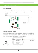
1.3 Working Principles 

Power subsystem

: Motor and gearbox provide power for the whole system. 

Speed reduction subsystem

: The speed reduction system control the lifting and falling speed of the 

boom. It makes the boom slow down when the boom stop movement. 

Spring balance subsystem

: A compression spring provides balance for the weight of the boom to 

keep the boom horizontal. 

Electric control subsystem

: The electric control subsystem consists of control board and position 

sensor.   

1.4 Specification Parameters of Product Series 

Appearance


Model


Boom Type


Standard Boom Length


Lifting/

Falling 

Speed


Fastening 

Mode


Note 

Gray 

appearance 

series


PB1010L 

Straight 

boom 

3 m 

1.8s 

Cabinet on 

the left 

The 3M standard 
configuration do 
not include the 
expansion boom. 
 

The device has 
220V and 110V 
two different 
types. 


PB1010R 

Straight 

boom 

3 m 

1.8s 

Cabinet on 

the right 

PB1030L 

Straight 

boom 

4 m

the expansion boom 

can be extended to 4.8 

m


3s 

Cabinet on 

the left


PB1030R 

Straight 

boom 

4 m

the expansion boom 

can be extended to 4.8 

m


3s 

Cabinet on 

the right


PB1060L 

Straight 

boom 

5 m

the expansion boom 

can be extended to 5.8 

m


6s 

Cabinet on 

the left


PB1060R 

Straight 

boom 

5 m

the expansion boom 

can be extended to 5.8 

m


6s 

Cabinet on 

the right


Содержание PB1000 Series

Страница 1: ...PB1000 User Manual Version 2 0 Date May 2017...

Страница 2: ...duct Installation 4 2 1 Installation Precautions 4 2 2 Cable Embedding 4 2 3 Cabinet Installation 4 2 4 Boom Installation 5 2 5 System Diagram 7 2 6 Wiring Diagram of the Push Button Station 8 Chapter...

Страница 3: ...painted cabinet It can be equipped with different types of straight booms Standard configuration of PB1030 and PB1060 include expansion boom Length of expansion boom can be up to 800mm Dimensions are...

Страница 4: ...ng Barrier User Manual 2 Figure 1 1C Dimensions of the PB1060 1 2 Components inside the cabinet Figure 1 2 Components inside the Chassis Four expansion bolts Position sensor Air switch Motor Gearbox H...

Страница 5: ...eters of Product Series Appearance Model Boom Type Standard Boom Length Lifting Falling Speed Fastening Mode Note Gray appearance series PB1010L Straight boom 3 m 1 8s Cabinet on the left The 3M stand...

Страница 6: ...protective sleeve and cable in advance 2 Route cables to be connected through protective sleeves 3 Use a tool to open a cable tray on the ground see figure 2 2 Figure 2 2 Cable embedding 2 3 Cabinet I...

Страница 7: ...as shown in Figure 2 4A 3 Remove the protection cover on the connection part as shown in Figure 2 4B 4 Adjust the length of the expansion boom only for 4M and 5M device and fasten the screw as shown...

Страница 8: ...he Decorative Cap Figure 2 4C Figure 2 4D Figure 2 4E Appearance of the Straight Boom Apply glue Main boom Main boom Wiping Off Spilled Glue Adjust the distance Fasten screws after adjusting the expan...

Страница 9: ...tem Diagram Installation Diagram for the Parking barrier and Wall The distance between the chassis and the wall should be greater than or equal to 100 mm The distance between the boom and the wall sho...

Страница 10: ...Parking Barrier User Manual 8 System Diagram 2 6 Wiring Diagram of the Push Button Station Push Button Station A standard power wire RVV3 1 0 A signal line RVV4 0 5 Control room...

Страница 11: ...he boom shakes during falling or lifting adjust position C The shaking that occurs during lifting is caused by the overlarge spring force In this case loosen the screws If the boom shakes during falli...

Страница 12: ...not fall down after the vehicle pass the boom will automatically fall down The wiring diagram is shown in the figure 4 1 Figure 4 1 4 2 Boom Illuminator System Boom Illuminator System includes 12V po...

Страница 13: ...When photo cell detect a vehicle the boom will not fall down after the vehicle pass the boom will automatically fall down The structure of photo cell is shown in the 4 3A and the wiring diagram is sho...

Страница 14: ...The installation of fan is shown in the 4 5A and the wiring diagram is shown in the figure 4 5B Figure 4 5A Figure 4 5B 4 5 Siren Siren requires 12V power supply User just need to place the siren on t...

Страница 15: ...Parking Barrier User Manual 13 Figure 4 6...

Страница 16: ...r 5 Device Maintenance 1 Maintain the boom Fix the reflective sticker 2 Tighten terminals connector of the device 3 Clear dust on components inside the cabinet Note that technicians should maintain th...

Страница 17: ...ss stop button on control board until D9 red light flash one time The operation successes and will delete all the registered transmitters Register the transmitter Press K4 setting button until D8 yell...

Страница 18: ...Parking Barrier User Manual 16 3 Wiring Diagram of the Mains Supply and Motor 4 Wiring Diagram of the Extension Board and Main Control Board Power supply Air switch Motor...

Отзывы: